Picture a sudden, catastrophic structural failure during the construction of a large-scale industrial facility. Under high winds, a newly erected structural bay buckles slightly, causing the roof deck to twist and pull apart. The culprit is not the heavy primary frames or the massive columns, which still stand perfectly straight.
Instead, the failure traces back to overlooked torsional warping, insufficient intermediate bracing, or a single miscalculated lap connection on the lightweight framing. When secondary elements distort under stress, they alter the unbraced length of primary rafters, threatening to pull the entire portal frame system down. The result is devastating project delays, soaring insurance liabilities, and astronomical on-site remediation costs that wipe out developer margins.
Fortunately, these costly structural errors can be systematically avoided by prioritizing the code-compliant engineering and selection of secondary steel members. High-quality, precisely manufactured secondary components secure the load path, bridging the gap between theoretical calculations and real-world field performance.
Why are secondary steel members vital?
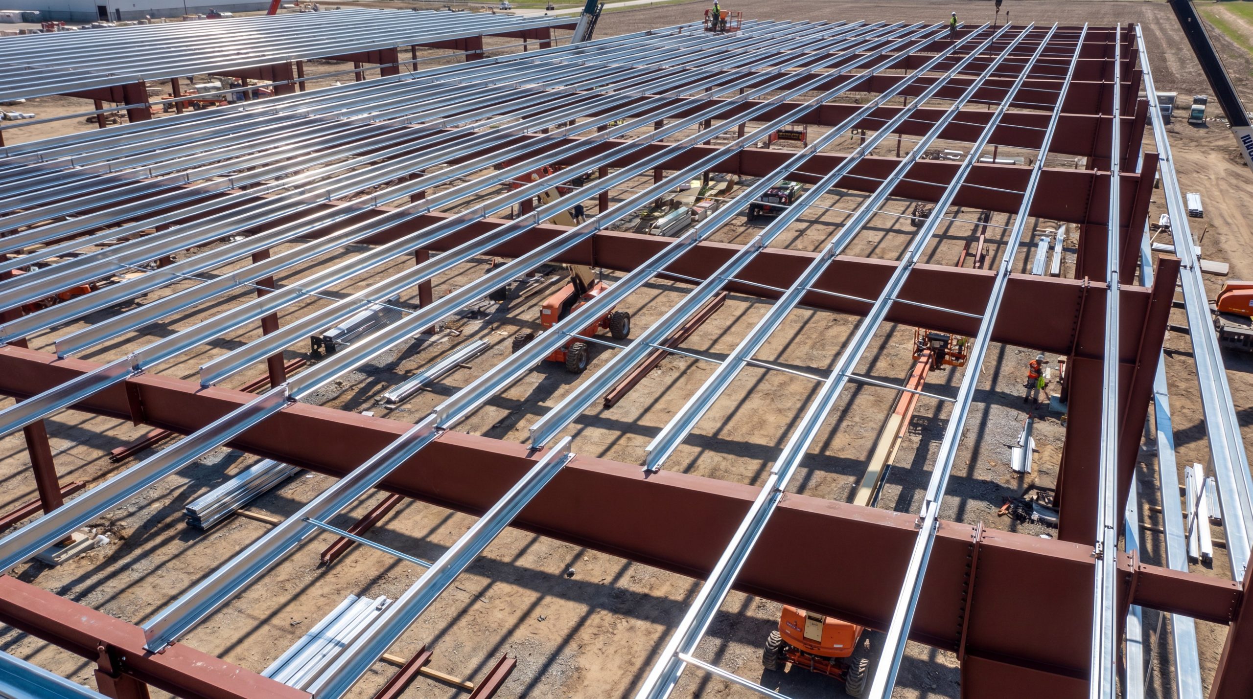
Defining Primary vs. Secondary Structural Frameworks
Primary structural frameworks, such as portal frames, heavy columns, and main rafters, carry major gravity and lateral loads directly to the foundation. In contrast, secondary steel members act as intermediate structural elements that distribute cladding, wind, and live loads directly to the primary frame. Without this secondary framing, primary columns and beams would require thick webs and massive flanges to resist unbraced lengths, which would significantly drive up material costs.
Lateral Bracing and Buckling Prevention Mechanics
Unbraced beams under bending are highly susceptible to lateral-torsional buckling (LTB), where the compression flange buckles sideways and twists the cross-section. Secondary steel members—specifically purlins, girts, and bracing—act as intermediate lateral restraints. By reducing the unbraced length (Lb) of the primary member’s compression flange, they increase its critical buckling moment (Mcr), as outlined in the AISC 360 LTB equations. This allows the primary frame to reach its full plastic moment capacity (Mp) safely.
Load Path Redistribution and Diaphragm Action
Secondary framing elements collect distributed surface loads from roof decking and wall cladding, transforming them into concentrated line loads or point loads acting directly on primary rafter nodes. Additionally, when metal deck sheets are securely fastened to secondary purlins and girts, they act as a semi-rigid structural diaphragm. This diaphragm action resists in-plane shear forces, stabilizing the entire building envelope against lateral drift during heavy usage.
Wind and Seismic Load Transfer Efficiency
During wind or seismic events, high lateral pressures act on building facades. Wall girts (secondary horizontal members) transfer these wind pressures from the cladding panels directly to the vertical columns. For seismic forces, secondary bracing elements, such as horizontal roof trusses or X-bracing, collect inertial forces and channel them down to the primary vertical lateral force-resisting systems (LFRSs).
Minimizing Torsional Effects on Main Framing
Eccentric loading on primary frame components introduces torsional moments that can cause premature structural failure. Secondary members help mitigate this risk. By connecting at precise grid locations and using double-sided connections or stabilizer plates, they apply opposing moments. This centers the load vector through the shear center of the primary frame, eliminating dangerous torsional warping stress.
“Secure your build with premium secondary steel members today!”
Email:sales@showhoo.com.cn
Phone/WhatsApp: + 86 186 7895 5927
How to design secondary steel members?
AISI and AISC Design Code Compliance
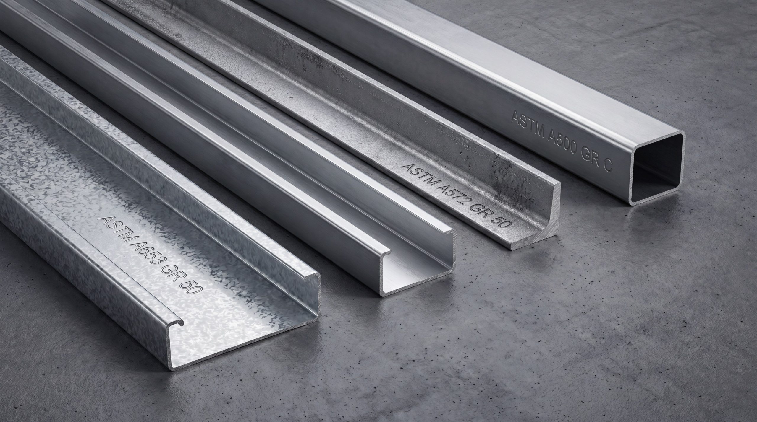
Secondary design requires adhering to two distinct design codes depending on the component thickness. When dealing with cold-formed steel (CFS) sections thinner than 3/16 in. (4.76 mm), engineers must apply the AISI S100 specification. This standard utilizes the Effective Width Method or the Direct Strength Method (DSM) to account for local and distortional buckling. For hot-rolled channels, structural angles, and hollow structural sections (HSS), designers must follow the AISC 360 design standard.
Calculating Wind Uplift and Gravity Loadings
Secondary roof framing is subjected to critical wind uplift, which often exceeds downward gravity loads on lightweight roofs. Designers must calculate loads using ASCE 7 load combinations. Under wind uplift, the bottom flange of a purlin experiences compression. Since this flange is not continuously restrained by roof sheet fasteners, it is highly susceptible to lateral-torsional buckling, requiring the installation of discrete bridging lines to stabilize the member.
Serviceability Limits and Deflection Criteria
Excessive deflection can damage brittle wall finishes, cause roof ponding, and compromise seals, leading to water intrusion. Design standard limits are typically defined as a fraction of the span length (L). Standard deflection limits for secondary members are shown below:
| Secondary Member Type | Gravity Load Limit | Lateral Wind Load Limit | Key Design Consideration | |
|---|---|---|---|---|
| Roof Purlins (supporting metal deck) | L/180 | L/150 | Protects standing seams of roof cladding | |
| Wall Girts (supporting metal panels) | — | L/120 to L/180 | Prevents exterior panel displacement | |
| Floor Joists (supporting plaster ceilings) | L/360 (Live Load) | — | Prevents brittle finish cracking | |
| Secondary members supporting glazing | — | L/360 or 3/4 in. (19 mm) max | Prevents glass fracture and seal failure |
Finite Element Analysis for Slender Sections
Traditional hand calculations can be overly conservative for complex geometries, such as sloped roof planes or members with web openings. Finite Element Analysis (FEA) using plate or shell elements allows engineers to model localized stress concentrations, shear lag, and cross-sectional distortional buckling. FEA is also useful for modeling the continuous elastic torsional restraint provided by the roof panels to the purlins.
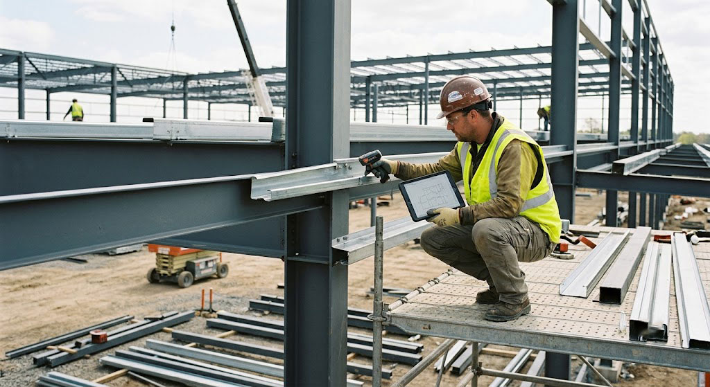
Software Modeling Integration (BIM and SAP2000)
Modern structural workflows rely on building information modeling (BIM) programs integrated with analysis packages. Using these tools, designers can model secondary steel members as physical entities with exact offset dimensions. This accounts for joint eccentricities and allows them to export precise analytical wireframe models to check reactions and deflections. This is particularly critical when building an energy-efficient industrial steel warehouse or heavy-duty manufacturing plant.
Which secondary steel members are best?
Cold-Formed Steel Z and C Purlins
Cold-formed Z and C sections are the industry standard for industrial roof purlins and wall girts due to their high strength-to-weight ratio. Z-sections feature unsymmetrical flanges of slightly different widths, allowing them to lap nestedly over interior support frames. Lapping creates a continuous double-thickness beam profile over support columns, which reduces mid-span bending moments and deflections. C-sections are mono-symmetrical, making them ideal for single-span run framing, eave lines, and framed openings around doors and windows.
Structural Eave Struts and Wall Girts
Eave struts are specialized profiles located at the intersection of the roof and exterior walls. They are designed to act as transitional members, supporting both the roof sheets and wall cladding. Eave struts must resist biaxial bending forces—such as wind pressure from the wall and gravity or uplift loads from the roof—while also acting as compression struts that transfer longitudinal wind loads between braced bays.
Hollow Structural Sections (HSS) for Bracing
Hollow Structural Sections (circular, square, or rectangular) offer excellent torsional resistance and balanced radius of gyration properties (rx≈ry). This makes HSS profiles highly efficient under compression loads, as they are less prone to weak-axis buckling compared to open-channel or angle sections. They are commonly specified as strut-ties, portal frame knee-bracing, and vertical cross-bracing.
Hot-Rolled Channel and Angle Sections
For heavy industrial plants, petrochemical facilities, or structures subjected to significant dynamic loads, hot-rolled channels (MC and C shapes) and unequal structural angles (L shapes) are preferred over cold-formed sections. Their greater web and flange thicknesses provide higher robustness against mechanical impact, reduce the risk of local buckling, and can be field-welded without reducing localized strength.
Yield Strength Grades (A653 vs. A1011)
Material specification directly dictates the structural capacity of secondary components. ASTM A653 covers steel sheets that are zinc-coated (galvanized) by the hot-dip process, which is the primary material specification for cold-formed Z and C purlins, typically ordered in structural grades such as Grade 50 (340 MPa) or Grade 55 (380 MPa). ASTM A1011 applies to hot-rolled carbon steel sheet and strip, which is typically specified for ungalvanized, black, or primed secondary sections that will receive post-fabrication coatings.
“Secure your build with premium secondary steel members today!”
Email:sales@showhoo.com.cn
Phone/WhatsApp: + 86 186 7895 5927
How to install secondary steel members?
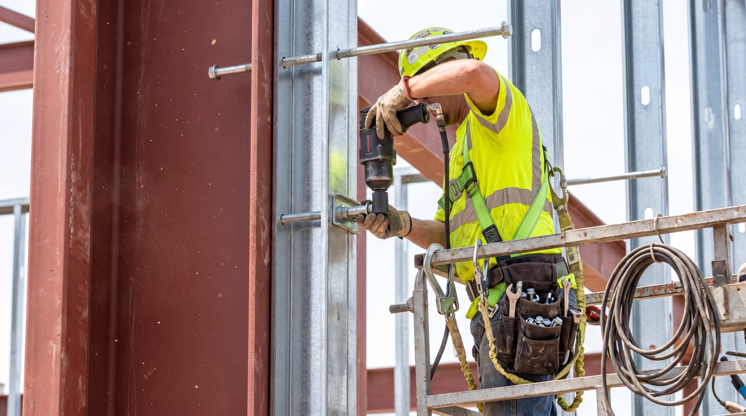
Bolted vs. Welded Connection Configurations
Bolting is the preferred method for assembling secondary steel members on-site. It speeds up erection, reduces field labor costs, and minimizes quality control issues in variable weather. Purlins and girts are bolted directly to welded clip plates on the primary frames. Field welding is generally restricted to specialized heavy secondary members or seismic structural retrofits. Welds must be executed by certified welders in accordance with AWS D1.1 (Structural Welding Code – Steel) or AWS D1.3 (Structural Welding Code – Sheet Steel).
Alignment, Plumbness, and Tolerance Standards
Secondary framing must be erected within strict structural tolerances to ensure cladding panels align correctly and seal properly. According to the AISC Code of Standard Practice:
- The deviation of secondary members from their planned horizontal alignment must not exceed 1/500 of the overall span length.
- Wall girt plumbness must be maintained within 1/4 in. (6.35 mm) over the height of any single frame column bay.
- Accumulated tolerances at structural joints must not force primary framing columns out of plumb alignment.
Sag Rod Installation and Bridging Systems
Due to their slender profiles, Z and C purlins installed on sloped roofs tend to rotate and sag down the slope under gravity loads before the roof deck is fully installed. To counteract this, structural designers specify sag rods or discrete bridging lines. Sag rods are solid steel threaded tension rods installed through the webs of purlins or girts to transfer downslope gravity components to a rigid ridge member. Bridging systems (such as bolted channels or cold-formed angles) are installed at mid-span or third-point intervals to prevent lateral torsional buckling during construction.
Fastener Selection (A325 Bolts and Self-Tapping Screws)
For secondary-to-primary connections, high-strength structural bolts, conforming to ASTM F3125 Grade A325, are used in diameters of 1/2 in. (12.7 mm) to 5/8 in. (15.9 mm). These connections are typically designed as snug-tightened bearings. For cladding-to-secondary connections, heavy-duty, self-drilling, self-tapping screws with integrated EPDM washers are used to attach metal roof deck sheets and wall panels to secondary steel members.
Field Modification and Framing Clearance Rules
On-site structural modifications must follow strict quality control protocols to maintain structural integrity:
- Hole Punching: Field-drifting or flame-cutting bolt holes is strictly prohibited. If modifications are required, holes must be cold-drilled or punched with sharp dies.
- Web Cutouts: Modifying the web of cold-formed purlins to route utility pipes or ductwork is prohibited unless explicitly approved and reinforced per AISI S100 guidelines.
- Clearance Offsets: Maintain a minimum edge distance of 1.5 times the bolt diameter from the center of any bolt hole to the sheared edge of a secondary plate.
How to protect secondary steel members?
Hot-Dip Galvanizing (HDG) Specification
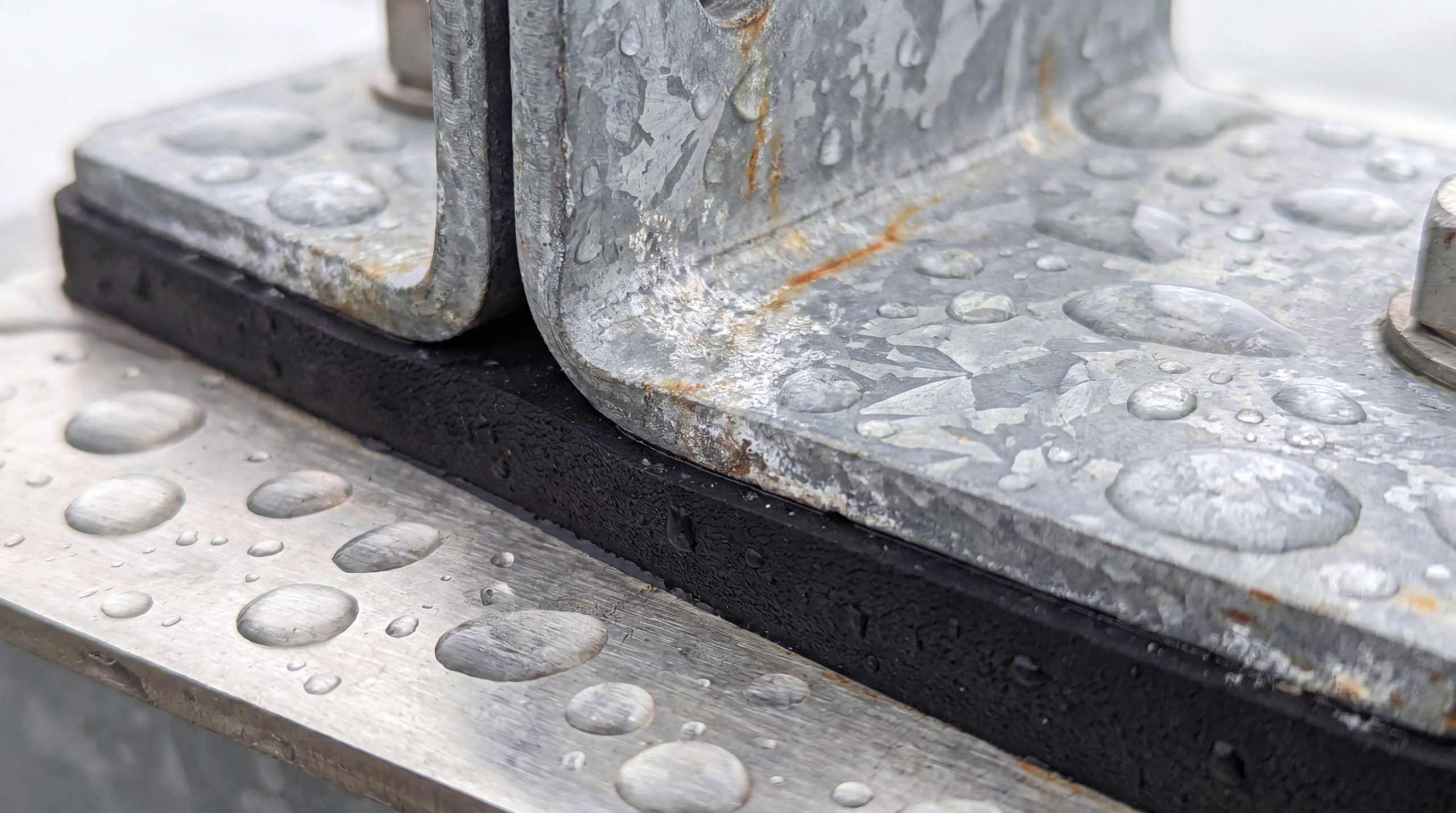
For long-term corrosion protection in unconditioned or industrial environments, hot-dip galvanizing per ASTM A123 or ASTM A653 is specified. For typical outdoor exposures, a minimum zinc coating class of G90 (0.90 oz/sq ft or 275 g/sq m total both sides) is recommended. This provides a sacrificial zinc layer that protects the steel substrate even if scratched, which is vital for maintaining the lifespan of any pre-engineered steel workshop .
Zinc-Rich Primers and Epoxy Coating Systems
For indoor, controlled environments, secondary steel is often protected with a shop-applied, fast-cure, rust-inhibiting alkyd primer. For highly corrosive environments, such as chemical processing plants or coastal facilities, a multi-coat paint system is specified:
- Base Coat: Zinc-rich epoxy primer (minimum 2.5 mils dry film thickness) to provide cathodic protection.
- Intermediate Coat: High-build polyamide epoxy coat to act as a physical barrier against moisture.
- Top Coat: Polyurethane coating (when exposed to outdoor UV radiation) to prevent color chalking and breakdown.
Dissimilar Metal Isolation to Prevent Galvanic Corrosion
When secondary steel members contact metals with different electrochemical potentials (such as copper piping, stainless steel brackets, or aluminum cladding), galvanic corrosion can occur. This reaction accelerates the corrosion of the more active metal (typically the carbon steel or zinc coating). To prevent this, install non-conductive isolation barriers, such as neoprene washers, EPDM gaskets, or heavy-duty polyethylene tapes, at the connection interface.
Regular Inspection Schedules for Structural Integrity
Secondary steel members should be inspected regularly to detect structural degradation before it leads to failure:
| Inspection Type | Frequency | Focus Area | Structural Metrics / Indicators | |
|---|---|---|---|---|
| Routine Walkthrough | Annual | Visual inspection of accessible roof purlins and wall girts. | Look for sagging, impact damage, water staining, or localized rust. | |
| Comprehensive Engineering Inspection | Every 5 Years | Detailed examination of primary-to-secondary joints and bracing. | Verify torque on structural bolts; inspect welds for cracks; measure web verticality. | |
| Post-Extreme Event | Immediate | Inspection of structural members in areas affected by high-wind or seismic activity. | Inspect for fastener pull-out, localized web buckling, or permanent deformation. |
Remedial Strategies for Localized Coating Failure
If inspections reveal localized coating failure or corrosion, technicians should execute repairs immediately using the following sequence:
- Surface Preparation: Wire-brush or sandblast the affected area to SSPC-SP2 or SP3 standards to remove all loose rust and scale.
- Solvent Cleaning: Wipe the surface with solvent to remove any residual grease, oil, and dust.
- Coating Application: Apply a cold-galvanizing compound per ASTM A780, ensuring the dry film contains a minimum of 95% pure zinc dust for effective cathodic protection.
- Quality Check: Verify the dry film thickness with a magnetic or electromagnetic gauge to ensure compliance with the original coating specification.
Value Engineering and Structural Optimization
Balancing Bay Spacing Against Secondary Tonnage
Value engineering in modern structural steel projects is heavily dependent on optimizing the relationship between primary frame spacing and secondary steel tonnage. As primary frame spacing increases from 20 ft (6.1 m) to 30 ft (9.1 m), the weight of the primary frames per square foot decreases, but the secondary purlins and girts must span further, requiring deeper profiles and thicker gauges. Finding the sweet spot minimizes total material consumption.
Standardizing Sections for Supply Chain and Procurement Efficiency
While structural calculations may allow for 10 different purlin sizes across a large project, standardizing the design to 2 or 3 profiles vastly simplifies procurement. Standardizing sections reduces lead times, reduces tooling changes during manufacturing, and prevents on-site errors during erection. This approach ensures a cost-effective, high-performing structural steel frame.
For premium pre-engineered designs, project budgeting assistance, or tailored structural specifications, feel free to reach out to our engineering team for a comprehensive structural review of your upcoming project.
“Secure your build with premium secondary steel members today!”
Email:sales@showhoo.com.cn
Phone/WhatsApp: + 86 186 7895 5927
Technical Reference FAQs
- Q1: What is the primary difference between cold-formed and hot-rolled secondary steel members?
Answer: Cold-formed secondary steel members (e.g., thin-gauge Z/C purlins) are manufactured at room temperature by rolling sheet steel. This process increases yield strength through work hardening but leaves the member susceptible to local, distortional, and lateral-torsional buckling. Hot-rolled members (e.g., structural channels and angles) are formed at high temperatures, resulting in thicker sections that are highly resistant to local buckling. They also lack the residual manufacturing stresses found in cold-formed members.
- Q2: How do sag rods prevent sag and rotation in deep girt/purlin systems?
Answer: Deep Z or C-purlins installed on sloped roof structures experience gravity load vectors that do not align with their principal cross-sectional axes. This offset creates a lateral force component that causes downslope sagging and torsional twisting. Sag rods provide discrete, intermediate vertical restraint along the span. They transfer these downslope forces to more rigid structural elements (like the ridge purlin or primary rafter frames) and keep the secondary members aligned.
- Q3: What are the maximum allowable deflection limits for secondary steel members supporting metal roofs?
Answer: According to standard international building codes and AISC design guidelines, the maximum allowable live-load-induced deflection for secondary steel roof purlins supporting standard metal decking is L/180 of the span. For secondary members supporting brittle finishes or plaster ceilings, the limit is increased to L/360 to prevent plaster cracking.
- Q4: How does galvanic corrosion occur in secondary steel, and how is it prevented?
Answer: Galvanic corrosion occurs when two electrochemically dissimilar metals (e.g., a galvanized steel purlin and a copper conduit or stainless steel bracket) are in direct contact in the presence of an electrolyte, such as moisture or condensation. The more active metal (zinc/steel) oxidizes rapidly. This is prevented by placing non-conductive isolation barriers, such as EPDM gaskets, neoprene washers, or heavy-duty polymer adhesive tapes, between the two metals.
- Q5: Can secondary steel members be field-welded without compromising their structural properties?
Answer: Field welding is acceptable for thick, hot-rolled secondary members, provided it is performed by certified welders in accordance with AWS D1.1. However, field-welding thin, cold-formed steel (CFS) sections is difficult and risks burning through the metal. It also destroys the localized corrosion-resistant zinc coating. When welding CFS, technicians must strictly follow AWS D1.3 and apply an ASTM A780 zinc-rich compound to restore corrosion protection.