
A steel-frame installation succeeds when documents, foundations, temporary stability, connections, and inspection evidence are controlled as one field system. Your fabricated frames may reach site while a crane and erection crew are booked, yet the anchor-rod survey, drawing revision, or temporary-bracing owner remains unresolved. That gap can turn paid crane hours into waiting time and a small fit-up issue into unsafe field alteration.
A controlled industrial steel framing installation plan resolves those interfaces before lifting starts. It assigns decisions, releases verified data, protects each temporary load path, and records acceptance at planned hold points. You gain a building process that can be audited rather than a sequence driven by verbal fixes.
1. What Controls Industrial Steel Framing Installation?
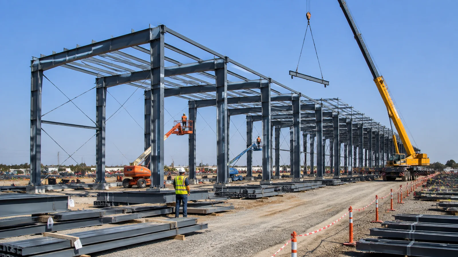
Industrial steel framing installation is controlled by approved project documents, a buildable erection sequence, competent field leadership, and defined acceptance authority. Permanent calculations describe the completed frame, while erection planning addresses incomplete states that may lack roof bracing, flange restraint, or diaphragm action. Your contract should name who designs temporary works, who controls lifting methods, and who accepts structural work.
Why does the temporary load path change during erection?
Here is the engineering reality: a completed portal frame and a partly erected frame behave differently. Wind can act on isolated columns, rafters may lack lateral restraint, and a stable bay may depend on guys until permanent bracing develops its intended load path.
- Identify each stage when permanent restraint remains inactive.
- Record temporary-brace locations, capacities, anchors, and removal gates.
- Link daily stopping points with a safe partially erected condition.
Who can approve a field change?
- This is the decision boundary: the field team reports the mismatch, but the designated engineering authority issues its disposition.
- Record member marks, dimensions, photographs, and affected connections in the request.
- Keep flame cutting, hole enlargement, anchor-rod movement, and weld repair outside informal site decisions.
Key Takeaway: Give every discrepancy one documented route from detection through engineering disposition and inspection closeout.
| Decision | Owner Named in Project Plan | Acceptance Record |
|---|---|---|
| Temporary stability | Erection planning authority | Approved sequence and bracing plan |
| Field discrepancy | Site lead and design authority | Closed technical query |
| Completed work | Assigned inspector | Signed hold-point record |
This map exposes responsibility gaps before they become lifting delays.
2. Which Documents Should Be Released Before Erection?
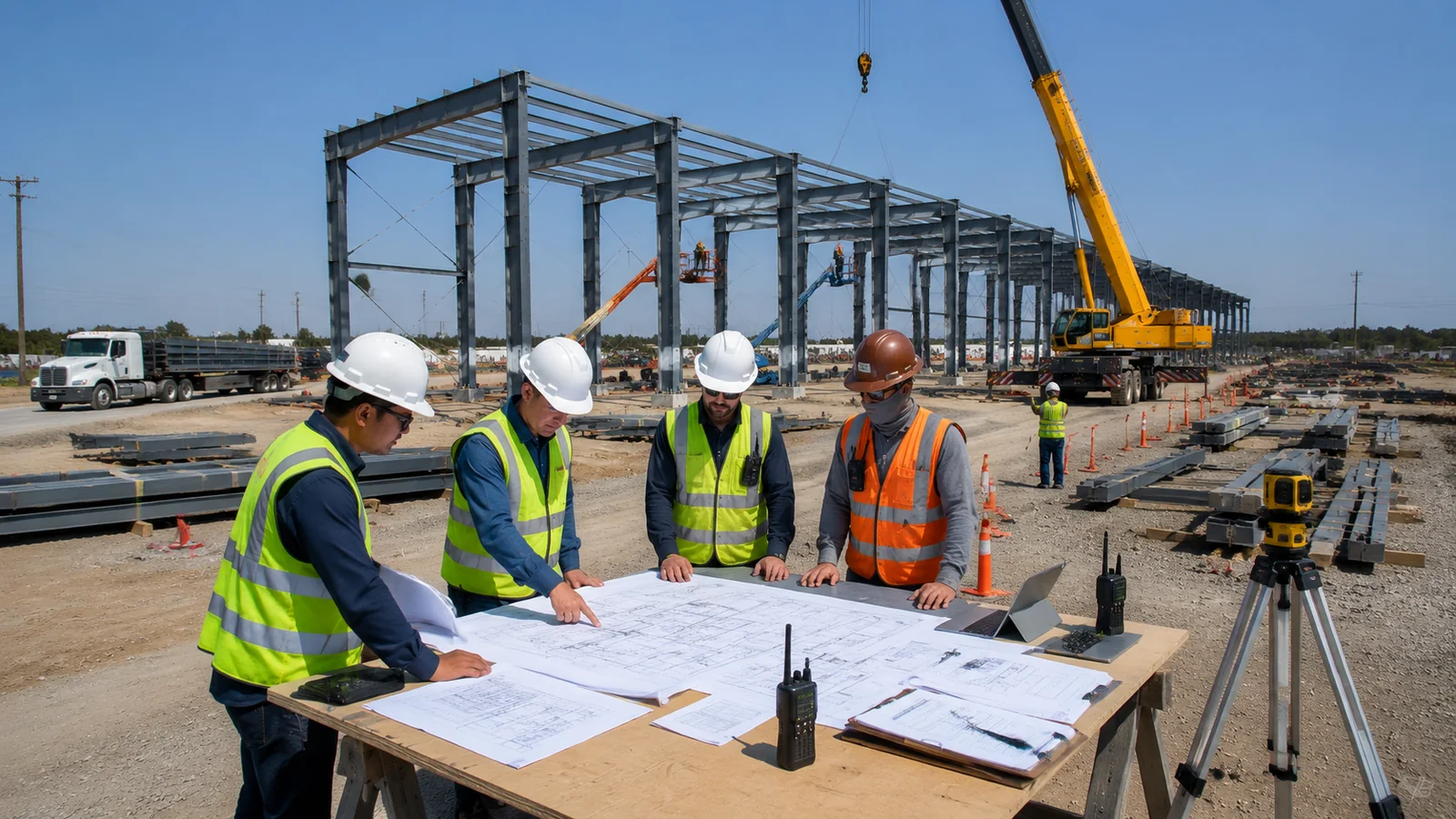
The released package should define what is installed, where each piece goes, how incomplete framing stays stable, and what evidence closes the work. A controlled industrial steel framing installation package ties erection drawings to current design documents, piece marks, connection details, delivery lists, survey control, lifting plans, and inspection procedures. A revision register should show one field status so superseded sheets don’t return through subcontractor copies.
Which drawings guide the site crew?
Look beyond a drawing stamp: useful field information connects grid lines, levels, member orientation, bolt assemblies, braced bays, and installation notes. Shop details help trace fabrication, while erection drawings organize placement; neither document should silently carry an engineering duty assigned elsewhere.
- Match every shipping piece mark with the erection drawing.
- Flag framed openings, crane beams, splices, and asymmetric members.
- Record approved queries beside affected drawing revisions.
What should the release register prove?
- Here is the release test: field, fabrication, survey, and inspection teams reference the same revision set.
- Include foundation release data, crane access review, rigging documents, and temporary-work approvals where applicable.
- Withdraw superseded files from printed packs and shared folders.
Key Takeaway: Mobilize lifting resources after a named controller confirms a coherent construction package, not after isolated drawings appear complete.
| Release Item | Field Use | Evidence |
|---|---|---|
| Erection drawing | Member location and orientation | Revision-controlled register |
| Sequence plan | Temporary stability and work order | Approved issue |
| Inspection plan | Hold points and witness roles | Signed inspection matrix |
A single register makes document readiness visible to buyer and site team.
3. How Should Foundations and Anchor Rods Be Accepted?
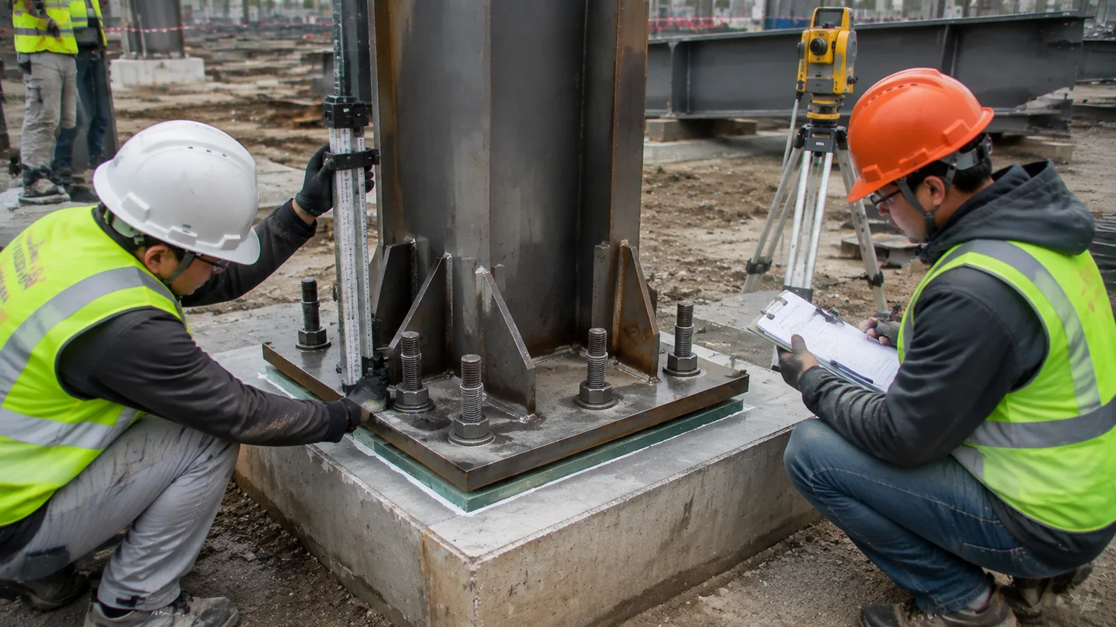
Foundations and anchor rods should be accepted through a documented survey, visual condition review, concrete release data, and base-plate fit check before steel mobilization. Industrial steel framing installation depends on the interface matching fabrication drawings, yet grid position alone doesn’t confirm projection, thread condition, bearing arrangement, or grout space. Record actual values against project tolerances and route deviations through the named engineering channel.
What should the pre-erection survey record?
The survey tells a larger story: each anchor group relates to a building datum, not a nearby edge that may carry its own error. Survey records should identify the instrument control, measurement date, grid coordinates, elevations, rod projection, and any obstruction around base plates.
- Check diagonal relationships across braced bays and frame lines.
- Protect threads and verify nuts can travel through required engagement.
- Confirm pedestal access permits base-plate setting and grout placement.
How should a mismatch be handled?
- Stop at the interface: describe the measured deviation before proposing a correction.
- Compare base-plate holes, edge distances, reinforcement constraints, and concrete condition with project data.
- Obtain written disposition before bending rods, enlarging holes, moving steel, or changing bearing details.
Key Takeaway: Accept foundations as a structural interface with traceable measurements, not as a visual civil-work handover.
| Check | Record | Release Gate |
|---|---|---|
| Grid and elevation | Signed survey report | Within project tolerance or dispositioned |
| Rod and thread condition | Photos and inspection sheet | Fit confirmed |
| Bearing and grout zone | Base detail review | Setting method approved |
Early interface evidence separates survey correction from steel rework.
4. How Should Steel Be Delivered, Sorted, and Protected?
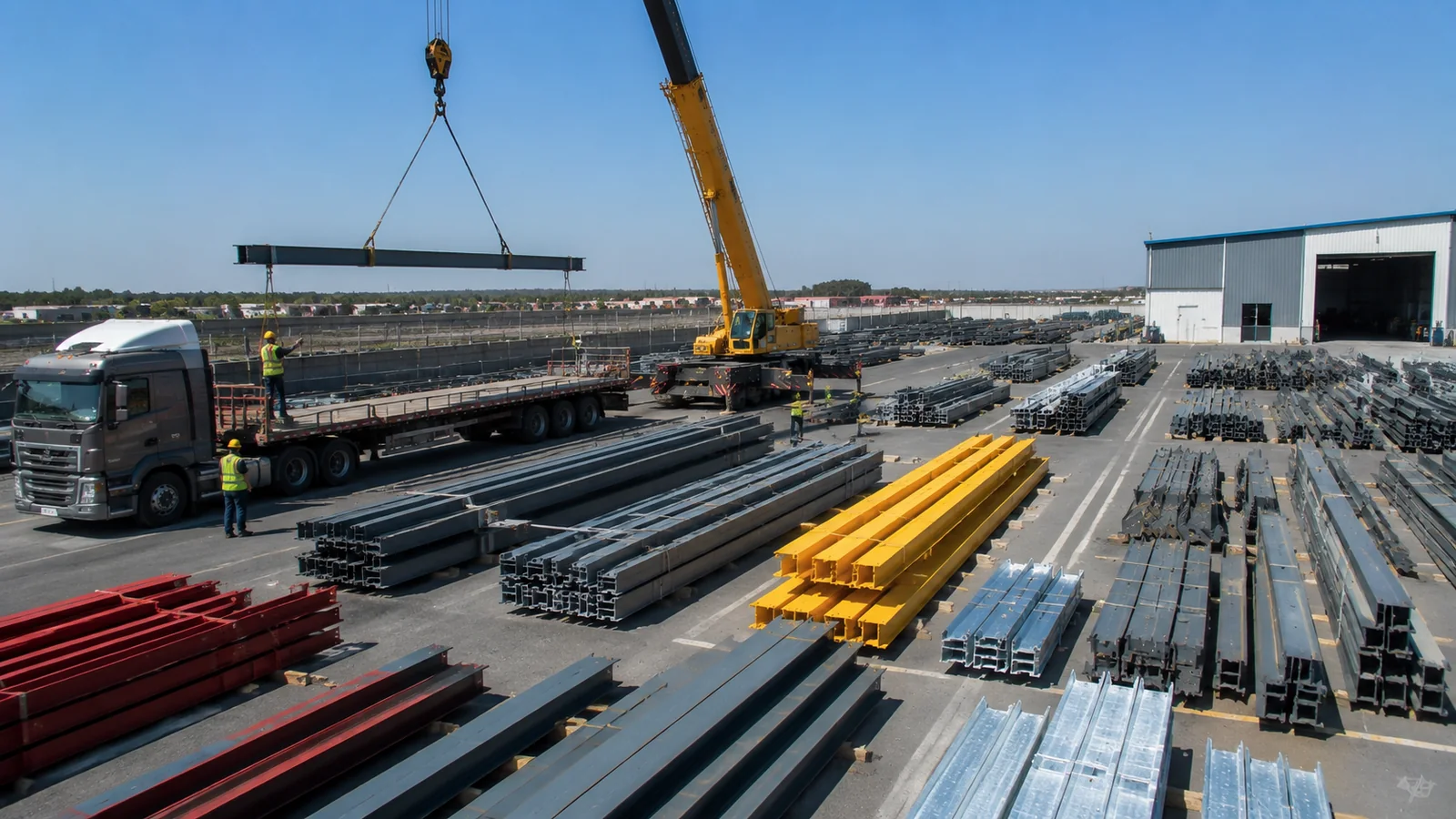
Steel should arrive in erection order, remain identifiable, sit on stable dunnage, and retain protected connection surfaces. A planned industrial steel framing installation links the fabricator’s packing list with crane reach, laydown capacity, bay sequence, and vehicle circulation. Poor staging creates double handling, coating damage, mixed bolt lots, and blocked access even when fabrication is accurate.
How does delivery order affect crane productivity?
Follow the hook path: pieces needed for a stable starter bay should be accessible without moving later-bay rafters. Laydown zones should preserve turning space, outrigger support areas, emergency access, and safe separation between people and mobile plant.
- Group primary members by bay and planned lift order.
- Store bolts and small parts in weather-protected, traceable containers.
- Keep long members supported at points that limit distortion.
What damage requires a receiving record?
- Watch the hidden interfaces: end plates, holes, threads, faying surfaces, and thin secondary members can suffer damage before erection.
- Photograph bent flanges, coating loss, water traps, missing marks, and contaminated connections during unloading.
- Use an approved repair system that matches coating type and surface preparation requirements.
Key Takeaway: Treat logistics as part of erection engineering because material location and condition affect sequence, safety, and fit-up.
| Receiving Control | Field Risk | Evidence |
|---|---|---|
| Bay-based packing | Crane idle time | Checked packing list |
| Supported storage | Member distortion | Laydown inspection |
| Coating protection | Premature corrosion | Damage and repair log |
The lowest handling count often produces the cleanest installation record.
5. What Erection Sequence Keeps a Portal Frame Stable?
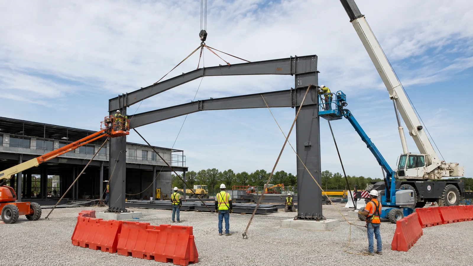
A portal frame stays stable when erection starts from an engineered stable unit and every new frame connects back through active restraint. Industrial steel framing installation commonly uses a braced bay as that unit, but its exact location and sequence depend on building geometry, wind exposure, cranes, openings, and temporary-work design. Purlins, girts, flange braces, and permanent diagonals should follow the planned sequence rather than lag behind a line of unsupported frames.
Why does the braced bay act as the starter unit?
Think in three dimensions: a portal frame may resist loads in its plane while remaining weak along the building length. A braced roof and wall system can form a spatial box that transfers longitudinal actions into selected foundations.
- Complete specified roof and wall bracing within the starter zone.
- Connect secondary members needed for rafter and column restraint.
- Maintain temporary guys until the removal gate is verified.
What should be checked before extending another bay?
- Use a stability gate: confirm connections, restraints, alignment, and weather limits for the erected unit.
- Review forecast site conditions and the permitted overnight configuration.
- Keep construction loads away from framing that lacks its designed support path.
Key Takeaway: Advance the crane only after the erected portion has a documented route for temporary loads into the foundations.
| Erection Stage | Stability Question | Release Evidence |
|---|---|---|
| Starter frames | What restrains longitudinal movement? | Bracing inspection |
| Bay extension | What restrains each new member? | Sequence sign-off |
| Work stoppage | Is the partial frame safe for site conditions? | Daily stability record |
This gate turns frame count into a controlled structural sequence.
6. How Should Bolted Connections Be Installed and Checked?
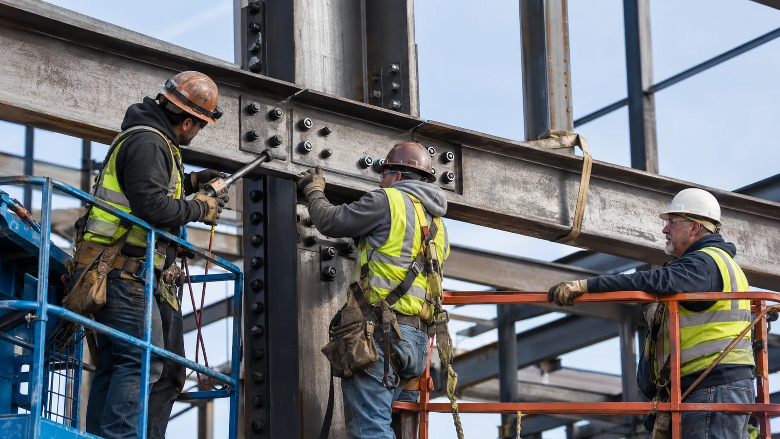
Bolted connections should be installed and checked through the joint type, specified bolt assembly, approved method, and inspection plan shown in project documents. During industrial steel framing installation, a torque value alone may not prove pretension because lubrication, thread condition, bolt lot, tool condition, and method affect the relationship. Inspectors need evidence suited to snug-tight, turn-based, tension-control, calibrated-wrench, or other specified procedures.
What should be verified before tightening begins?
Start with the joint, not the tool: confirm bolt grade, diameter, length, washers, lot identity, hole condition, and required faying-surface condition. Protect assemblies from dirt, moisture, mixed lots, and uncontrolled lubrication changes.
- Run required preinstallation verification with the site lot and method.
- Confirm connected plies are brought into the specified contact condition.
- Mark rejected bolts so they cannot return to active stock.
Which records show the connection was accepted?
- Match evidence to method: a visual spline check supports one system, while another method needs rotation marks or calibrated equipment records.
- Record inspection timing because some observations occur during installation.
- Trace repaired holes, substituted bolts, and field welds through approved dispositions.
Key Takeaway: Ask how each joint requirement will be verified before tightening starts, then capture evidence while it remains observable.
| Connection Evidence | What It Confirms | Common Gap |
|---|---|---|
| Bolt lot record | Assembly traceability | Mixed containers |
| Method verification | Site procedure capability | Generic torque assumption |
| Installation log | Completed inspection | Check performed too late |
Method-specific records are more useful than a blanket statement that bolts were checked.
7. How Are Line, Level, Plumb, and Tolerances Controlled?
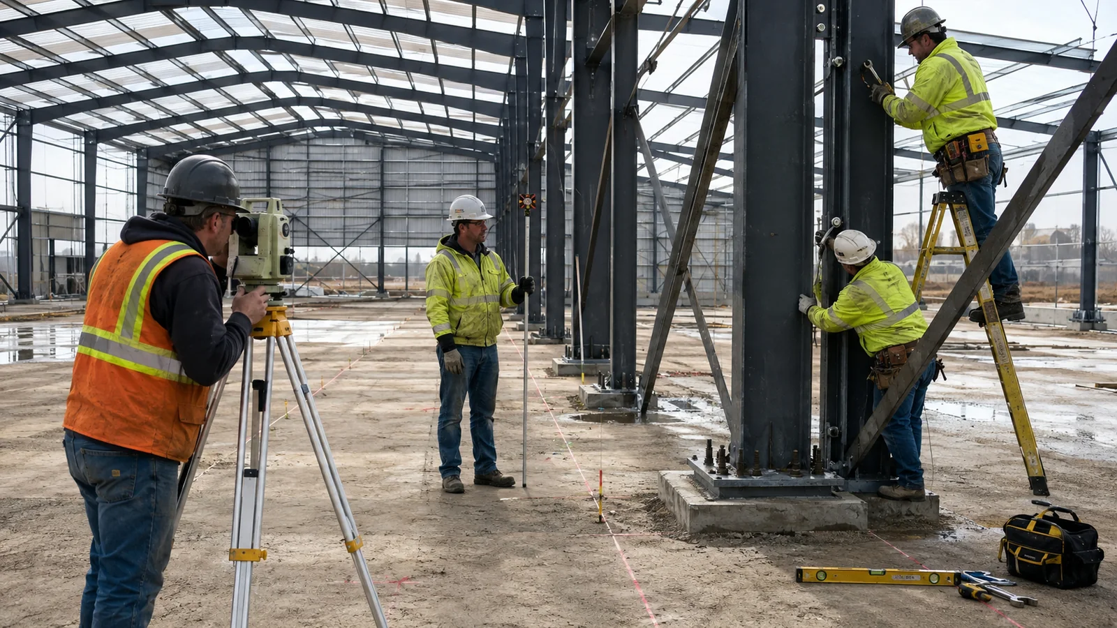
Line, level, plumb, and tolerances are controlled from an agreed datum through staged survey readings and documented adjustment points. Industrial steel framing installation should track cumulative drift across bays rather than checking only isolated columns. Temperature, temporary guys, loose connections, crane loading, and uneven bearing can change readings, so each survey should state the structural condition observed.
How should the survey control network be established?
Fix the reference before the frame moves: use stable control points independent from members being adjusted. Share grid and elevation references among civil, steel, crane-rail, equipment, and envelope teams so each trade doesn’t create a competing baseline.
- Protect survey monuments from plant movement and excavation.
- Record instrument setup, observation time, and relevant site condition.
- Check long runs at intermediate bays to catch accumulating error.
When should alignment be accepted?
- Read the sequence behind the number: an acceptable reading on loose framing may change after bracing and connection completion.
- Compare results with the project standard, contract tolerance, and intended interface.
- Close deviations through adjustment or approved disposition before dependent work hides access.
Key Takeaway: Accept geometry at defined structural stages and preserve the survey record that supports each downstream trade.
| Survey Stage | Structural Condition | Buyer Use |
|---|---|---|
| Column setting | Bases adjustable | Detect local interface error |
| Braced frame | Restraint active | Control cumulative drift |
| Handover | Connections complete | Release cladding and equipment |
Staged readings reveal movement that a single handover survey can miss.
8. How Should Secondary Steel and Cladding Be Coordinated?
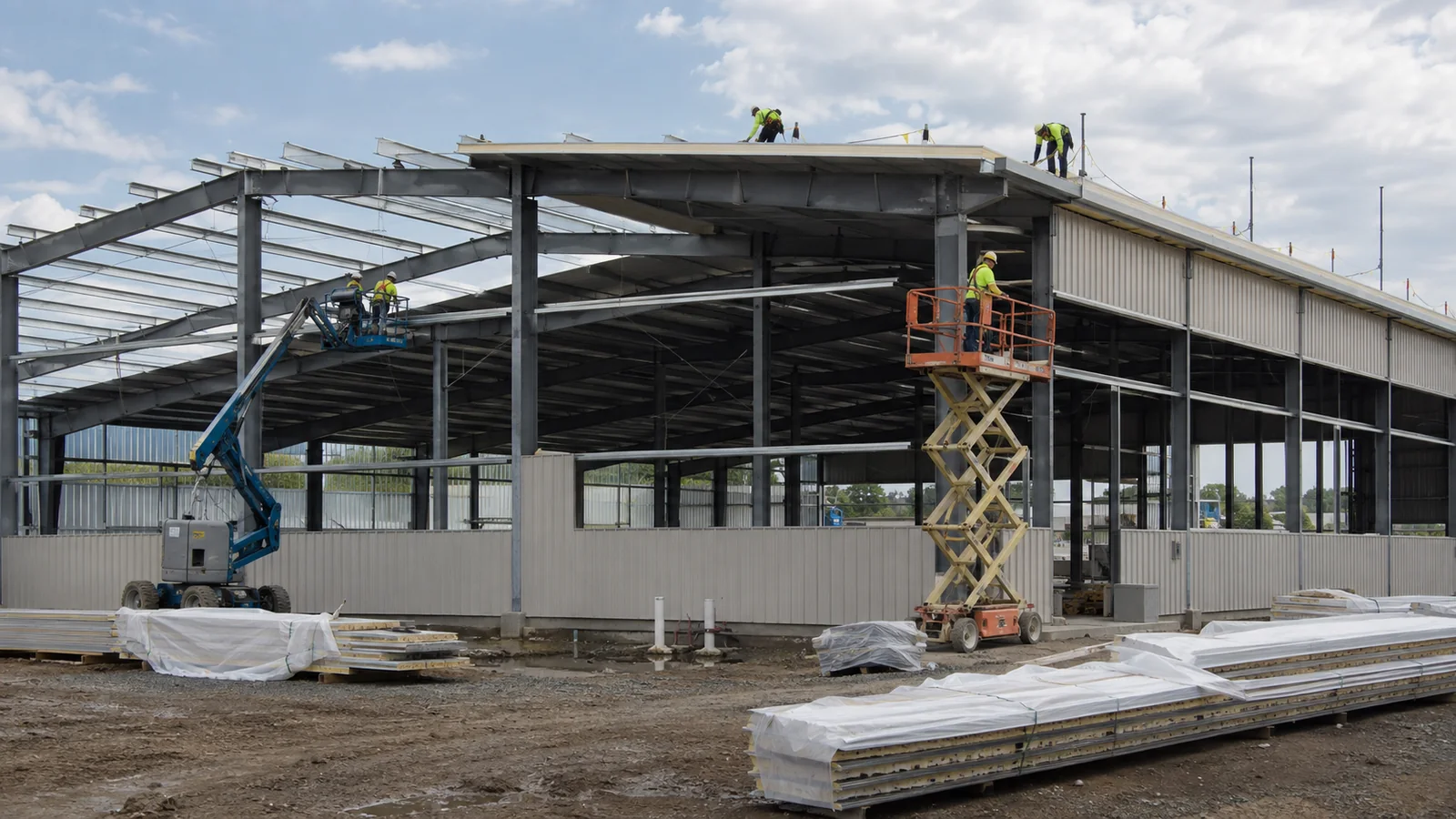
Secondary steel and cladding should be coordinated through restraint requirements, frame geometry, opening details, fastening patterns, and water-management interfaces. In industrial steel framing installation, purlins and girts may do more than carry panels; selected members, flange braces, sag systems, and eave struts can restrain primary steel. Removing or delaying them without review can alter both temporary behavior and completed performance.
Which secondary members affect frame restraint?
Trace every restraint point: a small brace may stabilize a large compression flange only after both ends are connected to the intended system. Piece marks, handed connections, laps, bridging, and brace orientation need field verification before loading increases.
- Confirm purlin and girt laps follow approved details.
- Check flange braces connect to the intended primary member zone.
- Record omitted members around openings for engineering review.
When should cladding work be released?
- Protect the interface: release panels after alignment, connection checks, and coating repairs are accessible and accepted.
- Coordinate penetrations, thermal movement, closures, gutters, and flashing with structural tolerances.
- Avoid forcing panels across a distorted frame because fasteners can mask stress until leakage or buckling appears.
Key Takeaway: Release the envelope after steel restraint and geometry are verified, not merely after the frame looks complete.
| Interface | Steel Check | Envelope Risk |
|---|---|---|
| Purlin line | Spacing and restraint complete | Roof waviness |
| Framed opening | Dimensions and diagonals verified | Door fit failure |
| Eave and gutter | Line, support, and falls coordinated | Water leakage |
Joint trade inspection catches problems before panels conceal their cause.
9. Which Inspections Should Close Each Installation Stage?
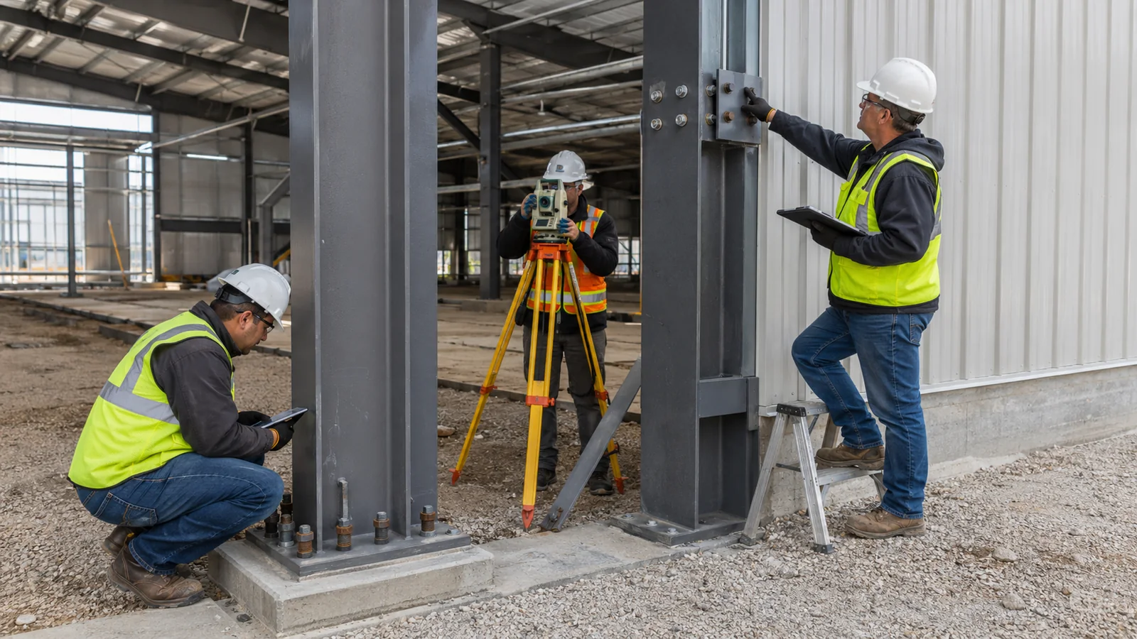
Each installation stage should close through a planned hold point that records condition, acceptance criteria, reviewer, evidence, and disposition status. Industrial steel framing installation benefits from gates at foundation release, starter-bay stability, connection completion, alignment, coating repair, envelope release, and structural handover. The inspection plan should identify witness and review points without transferring the erector’s work control to the buyer.
How should hold points follow construction risk?
Inspect before access disappears: anchor rods become hidden by base plates, bolts become difficult to observe, and bracing connections vanish behind panels. Place hold points where correction remains practical and where the next activity would hide evidence or lock geometry.
- Link each hold point with a drawing, procedure, and acceptance field.
- Name who can release work when the planned reviewer is absent.
- Prevent unsigned forms from becoming automatic acceptance.
What belongs in the handover quality file?
- Build the file during erection: collect survey reports, bolt records, weld reports, material traceability, coating repairs, and closed nonconformance records by bay.
- Include approved field changes and current as-built information.
- Reconcile open items against the punch list before structural release.
Key Takeaway: A handover file should reproduce the decision trail from delivered component through accepted structure.
| Hold Point | Evidence | Release Condition |
|---|---|---|
| Foundation | Survey and condition report | Deviations closed |
| Frame and connections | Stability, bolt, weld, and survey records | Dependent work released |
| Handover | As-built and closeout package | Open items assigned |
Evidence organized by stage gives buyers a usable record rather than a late document dump.
10. How Can Buyers Reduce Installation Risk Before Award?
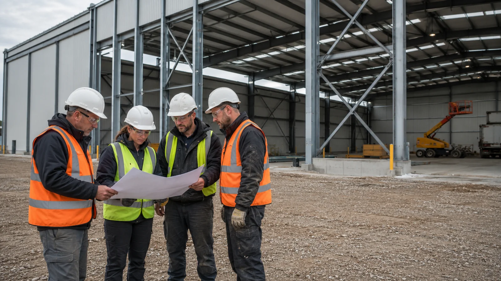
Buyers can reduce installation risk by pricing responsibilities, site readiness, temporary works, evidence, and change control inside the RFQ. A procurement-led industrial steel framing installation scope should state who supplies erection drawings, cranes, access, survey control, temporary bracing, connection verification, coating repair, and handover records. Comparable bids emerge when each contractor prices the same boundary rather than hiding exclusions in assumptions.
Which bidder evidence deserves technical review?
Ask for the proposed team, not a generic profile: review the erection lead, survey capability, lifting approach, quality procedure, and experience with comparable portal-frame geometry. Test how the bidder would manage an anchor-rod mismatch, a weather interruption, a damaged coating, and an unapproved field change.
- Request a preliminary sequence and site logistics concept.
- Compare inspection staffing with planned work fronts.
- Review subcontracted duties and engineering interfaces.
What should the final scope make measurable?
- Turn promises into deliverables: list release documents, hold points, response routes, records, and handover format.
- Define site-ready conditions and the process for reporting fabrication or foundation deviations.
- Ask Showhoo to coordinate design, fabrication data, packing logic, and technical support around your project delivery plan.
Key Takeaway: If you want a buildable steel package with traceable installation interfaces, contact us today and share your site data, loads, layout, schedule constraints, and local requirements.
| RFQ Deliverable | Bid Comparison Question | Contract Evidence |
|---|---|---|
| Erection responsibility map | Are all interfaces priced? | Scope matrix |
| Preliminary sequence | Is temporary stability considered? | Method submission |
| Quality closeout plan | Can acceptance be audited? | Handover index |
Showhoo’s position is simple: sound steel buildings begin with engineering that can be fabricated, erected, checked, and handed over with clarity.
Share Your Project Data And Get Technical Guidance !
Email:sales@showhoo.com.cn
Phone/WhatsApp:+86 186 7895 5927
Frequently Asked Questions
Q1: Can I let the erection contractor correct misaligned anchor rods?
Not without the project’s written disposition route. Anchor-rod changes can affect anchorage, reinforcement, base-plate behavior, and temporary column stability, so record the deviation and obtain the assigned engineering approval before work proceeds.
Q2: What’s the best way to confirm a braced bay is complete?
Use the approved erection sequence and an inspection record. The check should cover specified roof and wall bracing, secondary restraint, connections, guys, anchors, alignment, and the conditions for removing temporary support.
Q3: How do I know if high-strength bolts were installed correctly?
Match the evidence with the specified installation method. Review bolt traceability, preinstallation verification where required, joint condition, installation observations, and signed records rather than relying on one generic torque figure.
Q4: Can I start cladding before the entire frame is complete?
It depends on the approved sequence and accepted structural condition. Early cladding changes wind exposure and can hide connections, so release it by area only after restraint, alignment, coating, and interface checks are closed.
Q5: What’s the best RFQ input for comparable erection bids?
Provide a responsibility matrix with site conditions and required deliverables. Include access, crane support assumptions, survey control, temporary works, inspection roles, field-change routing, weather planning, and handover evidence.