
Shopping mall roof drainage design should move the code-defined storm from every roof zone to an approved discharge point while limiting ponding, leakage, overflow hazards, and operational disruption. A developer may approve a large steel roof around parapets, atriums, plant zones, and canopies, then find that late outlets conflict with purlins, shopfronts, electrical rooms, and underground drainage. Define shopping mall roof drainage design as a coordinated structural, roofing, plumbing, facade, and civil package before steel and panels are released.
1. What Should the Drainage Design Basis Define?

The design basis should define rainfall data, roof catchments, slopes, allowable water depth, primary and emergency routes, discharge points, durability, maintenance, and responsibility. It should state which local building, plumbing, stormwater, and structural requirements govern the project rather than transferring that decision to a component supplier.
Which inputs change the system?
Start with a coordinated roof plan divided into hydraulic catchments, including walls and upper roofs that discharge onto lower areas.
- Project coordinates and authority-approved rainfall intensity and duration
- Roof areas, pitches, valleys, sumps, parapets, canopies, and level changes
- Structural ponding and rain-load criteria from the engineer of record
- Primary outlet, gutter, downpipe, and underground drainage locations
- Secondary overflow route and safe visible discharge
- Debris, maintenance, corrosion, freeze, cyclone, and public-safety conditions
Illustrative scenario: an upper cinema roof drains onto a lower retail canopy that was sized only for its plan area. During an intense storm, the lower gutter overtops above an entrance, water reaches the facade, and tenants lose access while several contractors debate scope.
Key Takeaway: Approve one catchment and discharge model before separate trades size their own components.
| Design-basis item | Owner | Evidence |
|---|---|---|
| Rainfall and code | Civil or hydraulic designer | Approved criteria sheet |
| Ponding limit | Structural engineer | Rain-load and stability criteria |
| Discharge route | Architect and civil designer | Coordinated roof-to-site plan |
The system is only as reliable as the assumptions shared across disciplines.
2. How Are Rainfall and Catchment Flow Calculated?
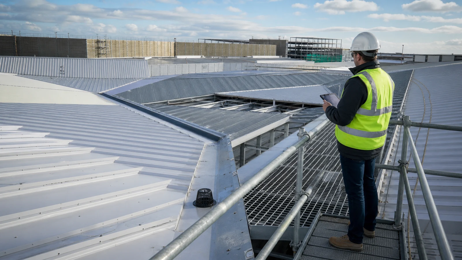
Rainfall and catchment flow are calculated from jurisdictional storm data, effective contributing area, runoff assumptions, and the hydraulic method required by local code. The metal building roof pitch affects travel time, valley geometry, gutter entry, and drainage zones, but pitch alone does not establish outlet capacity.
What should a buyer expect in the calculation package?
The package should map each catchment to its outlet and show how upper roofs, walls, wind-driven rain allowances, and blocked-primary cases are treated. For simple rational-method concepts, flow is proportional to rainfall intensity, runoff coefficient, and catchment area, but the engineer should use the adopted code formula and units.
- Source, edition, duration, and return period of rainfall data
- Effective area assigned to each gutter, valley, drain, or scupper
- Hydraulic head assumed at outlets and overflow devices
- Capacity of gutters, downpipes, bends, offsets, and leaders
- Effects of screens, strainers, debris, and partial blockage where required
- Interface with site stormwater capacity and permitted discharge rate
Failure chain: the roof supplier sizes an eaves gutter from horizontal roof area, while the facade designer directs a tall wall and canopy into the same run; actual inflow exceeds the documented basis and overtopping occurs at the most public elevation.
Key Takeaway: Require a catchment-by-catchment calculation tied to labeled roof drawings.
| Calculation input | Verification | Buyer risk if missing |
|---|---|---|
| Rainfall intensity | Authority source and edition | Undersized flow path |
| Effective area | Roof drainage plan | Unassigned contributing surfaces |
| Hydraulic head | Outlet detail and method | Capacity overstated |
Every calculated flow should have one visible route on the drawings.
3. Why Are Primary and Overflow Routes Both Needed?
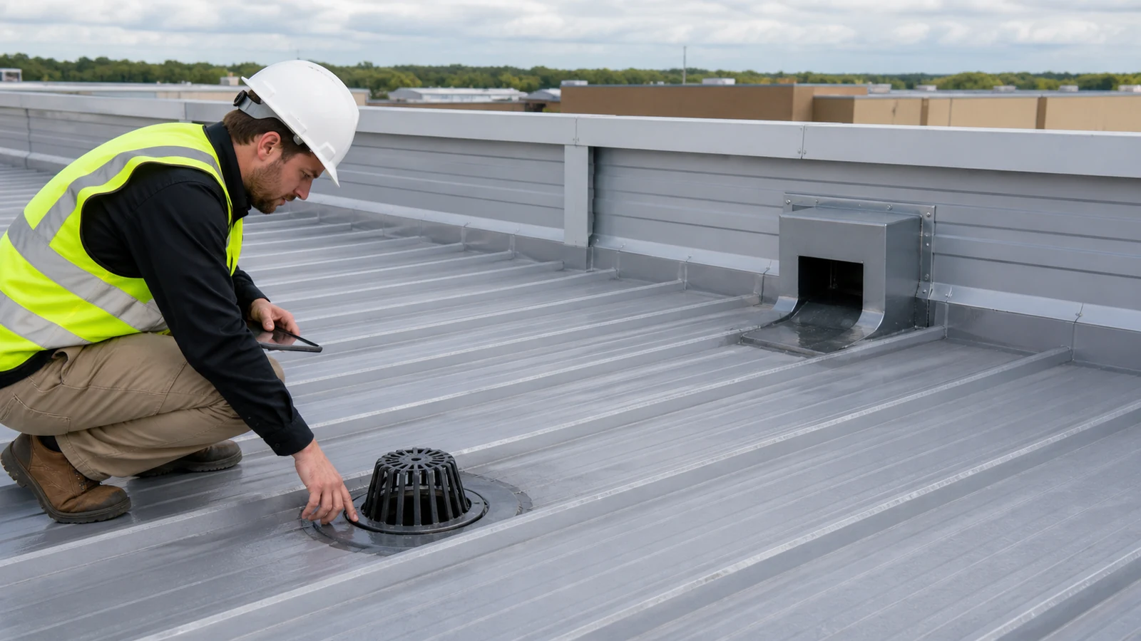
Primary and overflow routes are both needed because strainers, gutters, drains, pipes, and underground systems can become restricted or fail. Shopping mall roof drainage design should provide an independent, observable emergency path wherever parapets or geometry can trap water.
How should the overflow strategy be reviewed?
The 2024 International Plumbing Code requires secondary drains or scuppers where perimeter construction can entrap water and requires primary and secondary inlets to remain independent when combined in one assembly. Other jurisdictions use different rules, so the responsible designer should document the adopted provision and structural water-depth limit.
- Set overflow inlet elevation from the allowable ponding depth, not a generic detail
- Route overflow where discharge is visible without endangering occupants
- Avoid connecting primary and secondary systems in a way that defeats independence
- Check the overflow path when the primary outlet is blocked
- Keep scuppers clear of facade joints, signs, doors, electrical equipment, and escape routes
Failure chain: an internal drain blocks, the overflow scupper sits above the structurally permitted water level, ponding increases frame and deck demand, and leakage begins through roof penetrations before overflow becomes visible.
Key Takeaway: Emergency drainage should activate before the roof reaches an unsafe or damaging water depth.
| System | Normal condition | Blocked-primary evidence |
|---|---|---|
| Primary | Design storm flow | Hydraulic calculation |
| Secondary | Normally dry or inactive | Independent capacity check |
| Structure | Limited water depth | Ponding and rain-load review |
Overflow elevation connects hydraulic design directly to structural safety.
4. How Does Ponding Affect the Steel Roof Structure?
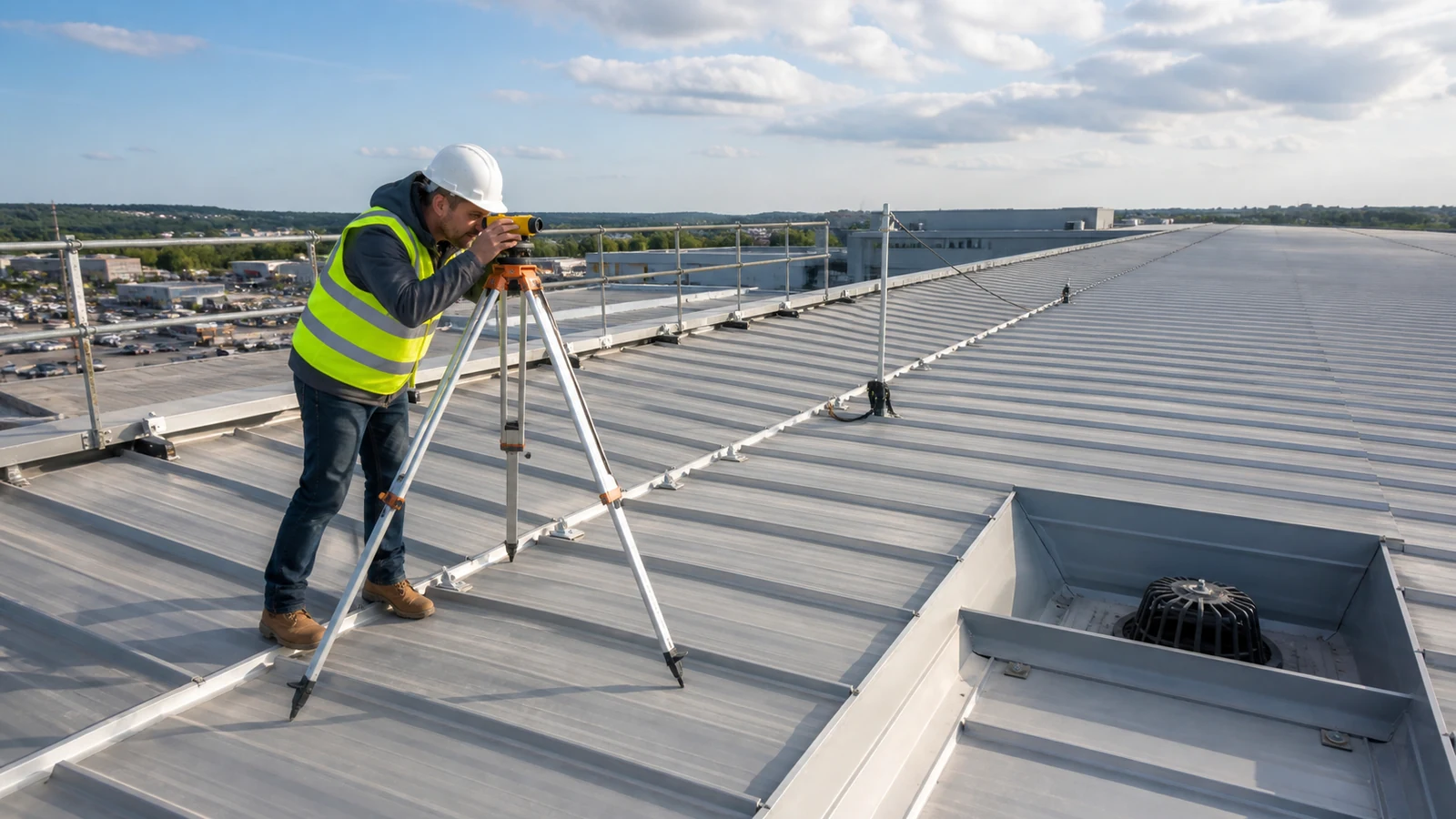
Ponding affects the steel roof by adding water load and potentially increasing deflection, which can attract more water and deepen the pond. The structural design for shopping mall roof drainage design should coordinate deck stiffness, purlin and frame deflection, construction tolerances, roof slope, outlet elevation, and overflow depth.
Which structural checks belong in the record?
The engineer of record should apply the adopted loading standard, including rain and ponding provisions such as those found in ASCE 7 where applicable. The analysis should distinguish nominal geometric slope from the lowest as-built surface under dead load and service conditions.
- Deflected roof profile and drainage direction under relevant loads
- Local low points at purlins, laps, gutters, sumps, and curb transitions
- Stability or ponding response when water depth increases with deflection
- Construction camber, tolerances, and survey requirements
- Temporary drainage during erection before permanent outlets operate
Inspection checkpoint: survey critical outlet, valley, gutter, and high-point elevations before roof completion. If tolerances reverse the intended fall, correct the supporting geometry or drainage detail through an approved design rather than relying on sealant.
Key Takeaway: Hydraulic drawings and structural deflection criteria should describe the same roof surface.
| Structural input | Drainage consequence | Evidence |
|---|---|---|
| Frame and purlin deflection | Changes flow path and depth | Serviceability analysis |
| Construction tolerance | Creates unintended low points | Roof-level survey |
| Overflow elevation | Limits stored water | Coordinated section |
The as-built low point controls where water collects.
5. How Should Gutters and Downpipes Be Detailed?
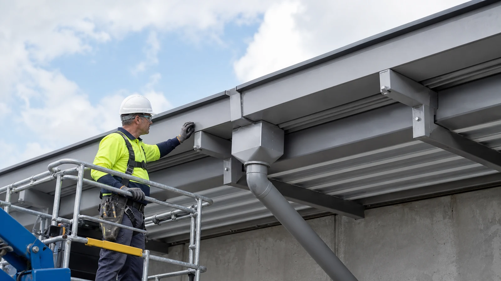
Gutters and downpipes should be detailed for hydraulic capacity, thermal movement, support, corrosion, cleaning, overflow behavior, and safe discharge. The roof and wall panel selection should coordinate coatings and dissimilar metals with drainage accessories rather than treating rainwater goods as a late add-on.
What should shop drawings show?
Recognized sheet-metal practice such as the SMACNA Architectural Sheet Metal Manual can guide gutters, scuppers, and downspouts, but project rainfall, wind, material, and code requirements control final design. Show continuous fall, high points, outlets, sumps, joints, brackets, anchors, expansion provisions, and connections to civil drainage.
- Net internal dimensions after liners, stiffeners, and jointing
- Outlet geometry and hydraulic head at design flow
- Bracket spacing and reactions under water, wind, and maintenance loads
- Expansion joints and fixed/sliding points for long metal runs
- Coating compatibility, cut-edge protection, and galvanic separation
- Cleanouts, strainers, leaf guards, access, and replaceable sections
Failure chain: a long dark-colored gutter is rigidly fixed between end walls; thermal movement distorts joints, fall is lost near a shop entrance, and repeated leakage damages soffits and finishes.
Key Takeaway: Detail the gutter as a moving, loaded metal assembly with a measurable hydraulic profile.
| Detail | Supplier submittal | Site check |
|---|---|---|
| Fall and outlet | Long section and capacity | Level survey |
| Movement | Expansion-joint layout | Fixed/sliding point inspection |
| Support | Bracket and load data | Spacing and fastener record |
Capacity on paper depends on geometry that installers can reproduce.
6. How Should Valleys, Parapets, and Penetrations Drain?
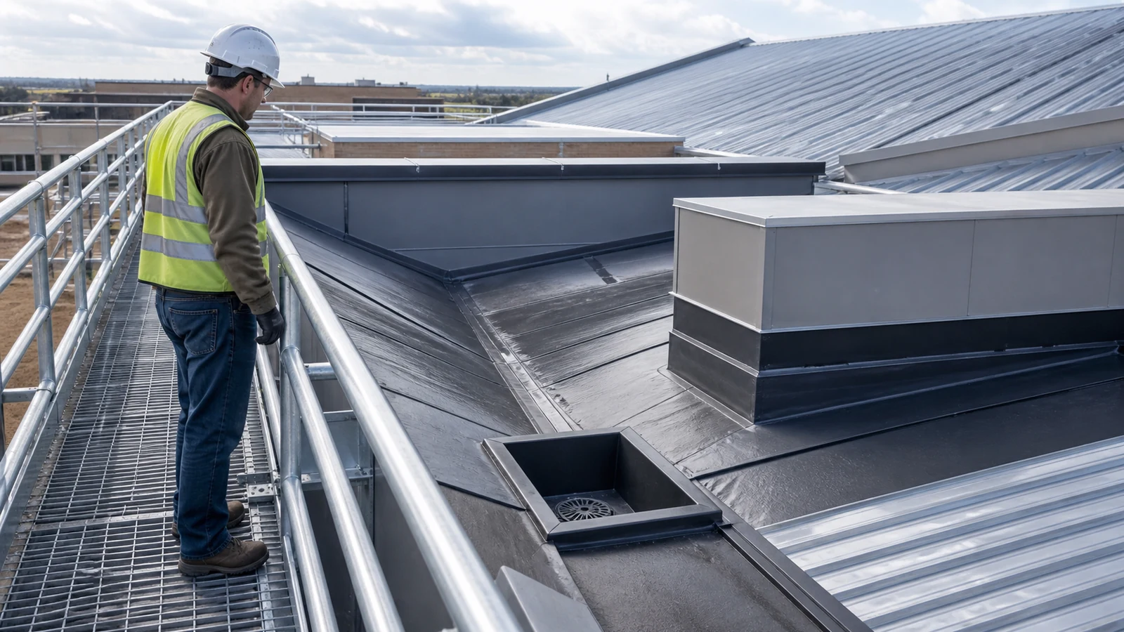
Valleys, parapets, and penetrations should drain without concentrating water at vulnerable flashings or creating hidden reservoirs. Shopping mall roof drainage design needs special sections where roof planes meet atriums, smoke vents, plant curbs, skylights, signs, and facade upstands.
Which interfaces deserve a representative mock-up?
Choose the most congested or repeated junction rather than a simple open roof bay. The mock-up should demonstrate support, membrane or panel laps, upstands, closures, overflow, sealant geometry, drainage direction, and access for inspection.
- Valley termination into a gutter or sump
- Through-parapet scupper and conductor head
- Roof-panel end lap near a low point
- Plant curb on the uphill or downhill side of flow
- Skylight, smoke vent, or atrium junction
- Cable, duct, pipe, and maintenance-walkway penetrations
Failure chain: a late duct curb is installed across a shallow drainage path, water backs up against a panel lap, capillary entry and fastener leakage occur, and the defect appears inside an occupied tenant zone far from the blocked path.
Key Takeaway: Coordinate water paths around every obstruction before curb and secondary-steel fabrication.
| Interface | Hold point | Acceptance evidence |
|---|---|---|
| Valley outlet | Before closure | Dimension and water-path inspection |
| Scupper | Trial installed unit | Mock-up and controlled-water test |
| Penetration | Before flashing concealment | Photo and detail register |
Complex transitions deserve earlier proof than repeated open roof areas.
7. How Do Purlins and Secondary Steel Affect Drainage?
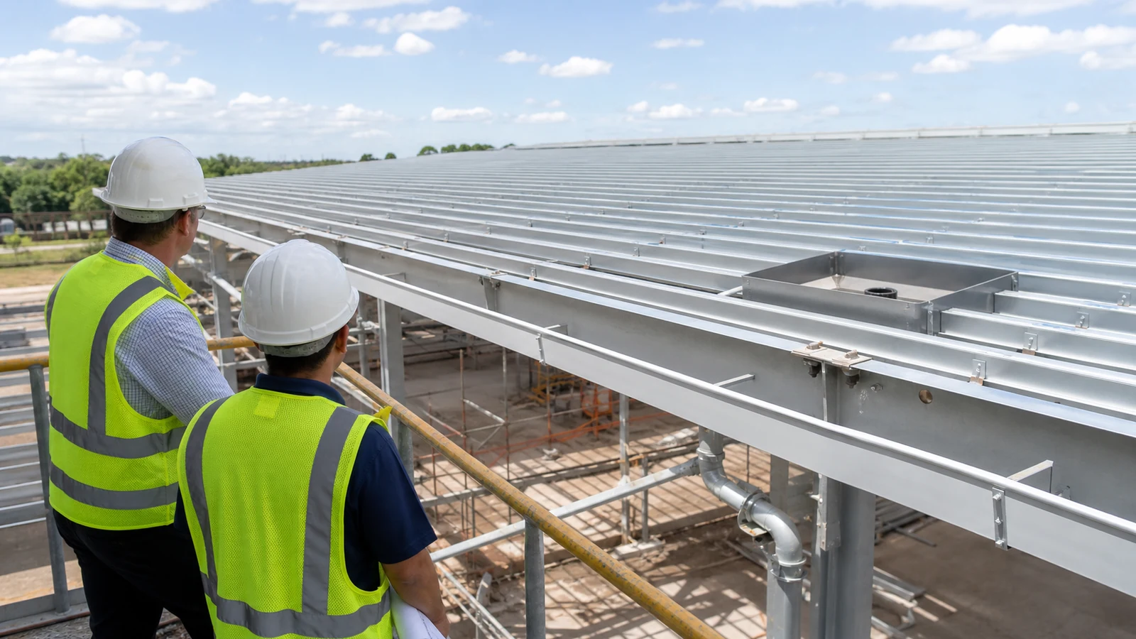
Purlins and secondary steel affect drainage by setting panel support elevations, stiffness, lap locations, curb framing, and gutter attachment. The roof and wall purlin design should include drainage-sensitive deflection and tolerance information, not only strength checks.
Which coordination changes are expensive when late?
Outlet sumps, internal gutters, large downpipe openings, parapet scuppers, and plant curbs can require trimmed purlins, headers, stiffeners, or relocated bracing. If these locations arrive after steel fabrication, site cutting can disrupt load paths, coatings, bolt access, and erection sequence.
- Reserve framed openings for drains, scuppers, and large leaders
- Keep bracing and service routes clear of cleaning access
- Coordinate gutter supports and reactions with eaves members
- Show panel lap direction relative to slope and prevailing weather
- Define permitted site holes and reinforcement approval process
Failure chain: a downpipe is shifted around a shopfront after steel release, the new route conflicts with an eaves brace, unapproved cutting occurs, and both structural repair and facade redesign are needed before opening.
Key Takeaway: Freeze drainage penetrations and support reactions with the secondary-steel model.
| Coordination item | Needed date | Evidence |
|---|---|---|
| Outlet and scupper locations | Before steel detailing | Federated roof plan |
| Support reactions | Before member design | Supplier load schedule |
| Site change | Before cutting | Engineer-approved repair detail |
Early geometry control protects both drainage and structural traceability.
8. Where Should Roof Water Discharge at Ground Level?
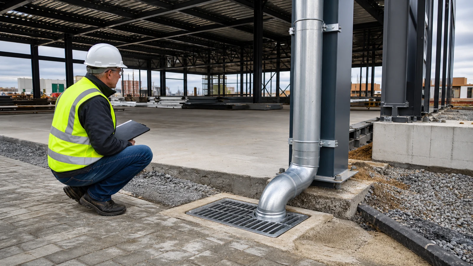
Roof water should discharge into an approved site system without flooding entrances, loading areas, foundations, neighboring property, or public routes. Shopping mall roof drainage design remains incomplete until every downpipe, scupper, and emergency discharge connects to a civil route with adequate capacity and maintenance access.
Which downstream interfaces need confirmation?
Coordinate leaders, underground pipes, attenuation, harvesting, oil or debris controls where required, and authority discharge limits. Keep visible overflow outlets conspicuous enough to indicate a primary blockage while preventing discharge over doors, accessible routes, electrical equipment, and emergency exits.
- Finished ground and pavement falls around each discharge point
- Downpipe protection in vehicle and delivery zones
- Flexible or detailed connections across movement joints and settlement zones
- Rodding, cleanout, inspection-chamber, and replacement access
- Backflow risk from municipal or site storm systems
- Construction-phase temporary routes before permanent civil works operate
Failure chain: a roof downpipe connects to an undersized yard drain that surcharges; water rises at the foundation, enters service penetrations, and the roofing contractor is blamed despite the downstream restriction.
Key Takeaway: Prove capacity and responsibility from roof catchment to final outfall.
| Interface | Responsible party | Handover evidence |
|---|---|---|
| Downpipe-to-leader | Roofing and plumbing | Connection inspection |
| Leader-to-site system | Civil contractor | CCTV or test record where specified |
| Overflow discharge | Architect and safety team | Visible safe-route review |
Roof and site drainage should be commissioned as one chain.
9. How Is the Drainage System Inspected and Tested?
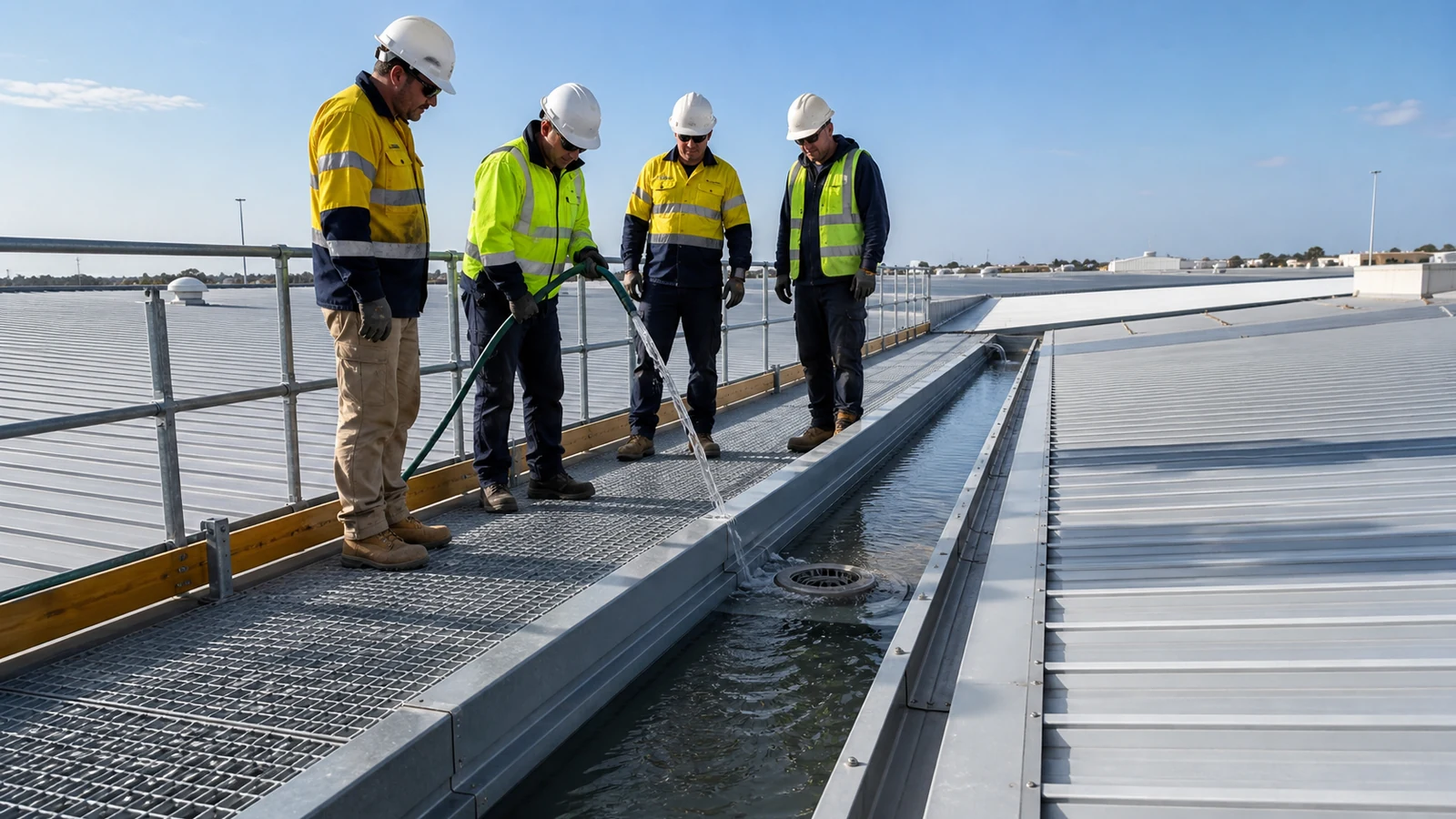
The drainage system is inspected and tested through dimension checks, level surveys, joint and coating inspection, controlled-water tests, blockage scenarios where specified, and maintenance-access review. Shopping mall roof drainage design should leave records tied to roof zones and outlets, not a single completion photograph.
What should the inspection and test plan contain?
Schedule hold points before gutters, liners, sumps, and penetration flashings become concealed. Coordinate tests so water does not overload incomplete drainage or damage internal finishes, and obtain designer approval for test rates and durations.
- Factory dimensions and coating records for fabricated gutters and sumps
- Trial gutter, outlet, scupper, and penetration inspections
- Roof-level and gutter-fall survey after structural loading stabilizes
- Controlled-water test at representative transitions
- Downpipe and underground route clearance confirmation
- Debris removal, strainers, labels, access, and maintenance demonstration
Acceptance checkpoint: reconcile the as-built outlet schedule with final catchment drawings and hydraulic calculations. Any relocated outlet or changed gutter section should trigger a documented design review.
Key Takeaway: Acceptance should verify capacity geometry, weathering, discharge continuity, and maintainability.
| Stage | Inspection evidence | Release decision |
|---|---|---|
| Fabrication | Dimensions, material, and coating | Ship or correct |
| Installation | Level, joints, support, and flashing | Conceal or repair |
| Handover | Test, cleanout, and as-built records | Accept or retest |
Traceable zone records shorten future leak and blockage investigations.
10. What Should Buyers Include in the RFQ?
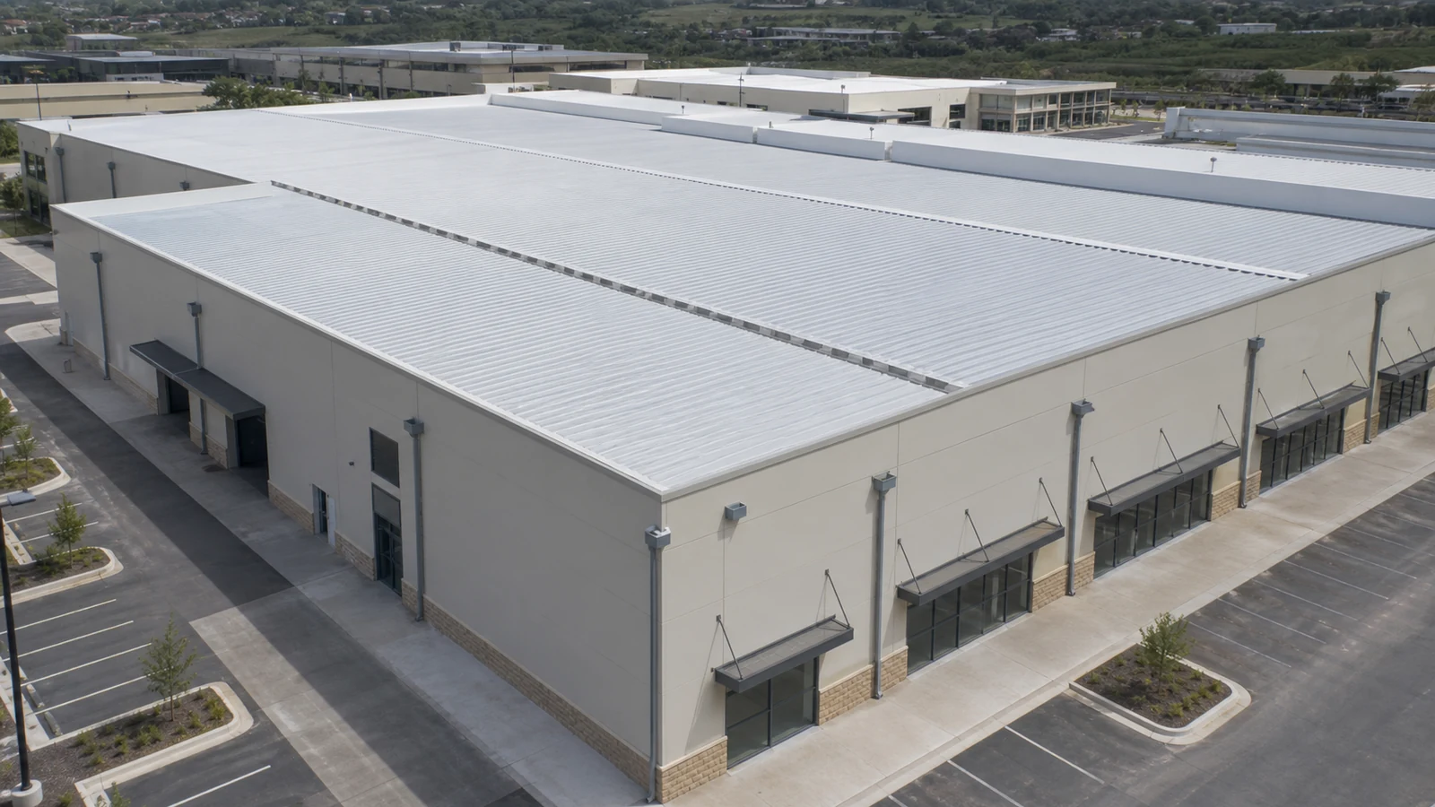
Buyers should include rainfall criteria, catchment drawings, structural limits, outlet schedules, materials, civil interfaces, testing, maintenance, and responsibility boundaries in the RFQ. A complete shopping mall roof drainage design package allows steel, roofing, plumbing, facade, and civil bidders to price coordinated scope instead of relying on exclusions.
Which deliverables make bids comparable?
Send architectural roof plans, sections, elevations, structural grid, preliminary levels, plant and penetration schedule, site drainage concept, climate basis, local code, program, and logistics constraints. Ask bidders to return calculations, assumptions, exclusions, material data, support reactions, shop drawings, hold points, testing, spares, and handover records.
- Catchment, primary, and secondary drainage calculations
- Roof, gutter, outlet, downpipe, and overflow schedules
- Structural rain-load and ponding coordination statement
- Responsibility matrix from roof surface to final outfall
- Fabrication, coating, packing, erection, and repair procedures
- Inspection, controlled-water test, maintenance, and as-built plan
Key Takeaway: Use one coordinated design basis to compare proposals, then view our complete steel structure solutions in relation to the wider retail project. Reliable commercial roofs begin with water paths that remain safe when one component is restricted.
| RFQ section | Bidder response | Buyer evaluation |
|---|---|---|
| Hydraulic basis | Calculation and assumptions | Capacity and code alignment |
| Interfaces | Responsibility and reactions | Scope gaps and late-change risk |
| Acceptance | Inspection and maintenance plan | Verifiable handover |
Comparable bids make every drainage boundary visible before award.
Get Expert Shopping Mall Roof Drainage Design Solutions Today !
Email:sales@showhoo.com.cn
Phone/WhatsApp:+86 186 7895 5927
Frequently Asked Questions
Can I size mall gutters from roof area alone?
No. Rainfall intensity, effective catchment, roof pitch, hydraulic head, outlet geometry, overflow strategy, and downstream capacity also affect sizing.
What’s the best overflow arrangement for a parapet roof?
It is project-specific. The arrangement should meet local code, remain independent where required, activate below the structural water-depth limit, and discharge visibly and safely.
How do I know if roof ponding is a structural risk?
Ask the engineer of record to evaluate rain load, deflection, drainage geometry, stability, and overflow elevation using the adopted loading standard and as-built levels.
Can downpipes discharge directly beside the foundation?
Only when the approved civil design manages the water safely. Uncontrolled discharge can erode soil, wet foundations, flood routes, or surcharge nearby drains.
What’s the best handover evidence for roof drainage?
Request final calculations, catchment and outlet schedules, level surveys, concealed-work inspections, water-test records, cleaned systems, as-builts, and maintenance access instructions.