Designing a steel beam involves a precise sequence of calculating loads, selecting material grades, and verifying structural stability against various limit states. You often face the daunting challenge of balancing architectural aesthetics with the rigid safety requirements of modern engineering codes. Failure to account for even a minor lateral force or deflection limit can compromise the integrity of your entire project, leading to costly redesigns or structural risks. This guide provides the solution by streamlining the steel structure design process into manageable steps that ensure safety, efficiency, and compliance.
1. What is the process of steel structure design?

The process of steel structure design follows a logical workflow starting from load identification and ending with final member verification. You must first understand the intended use of the building to establish the preliminary framework for all calculations. Professional steel structure design requires you to integrate material properties with geometric constraints to create a stable skeletal system.
1.1. Establishing the Design Workflow
Success begins with a clear definition of the structural intent and the surrounding environmental constraints. You need to gather all architectural blueprints to determine the spans and support locations for every critical beam.
Here is the deal:
- Identify the beam’s primary function.
- Determine the required clear spans.
- Select the appropriate design code (AISC/Eurocode).
1.2. Why is compliance mandatory?
Building codes provide the safety margins necessary to protect life and property under extreme conditions. Every steel structure design must undergo rigorous checks to ensure it meets both strength and serviceability standards.
You might be wondering: “How do I choose between LRFD and ASD?” The answer depends on your local jurisdiction and specific project requirements.
Key Takeaway:A structured workflow ensures that no critical load path or safety factor is overlooked during the engineering phase.
Summary Table: Design Initiation
| Stage | Primary Task | Outcome | |
|---|---|---|---|
| Preliminary | Site Analysis | Design Constraints | |
| Planning | Load Path Mapping | Structural Layout | |
| Selection | Code Identification | Safety Standard |
This initial phase sets the benchmark for all subsequent mathematical modeling and material selection.
2. Which examples use this steel structure design?
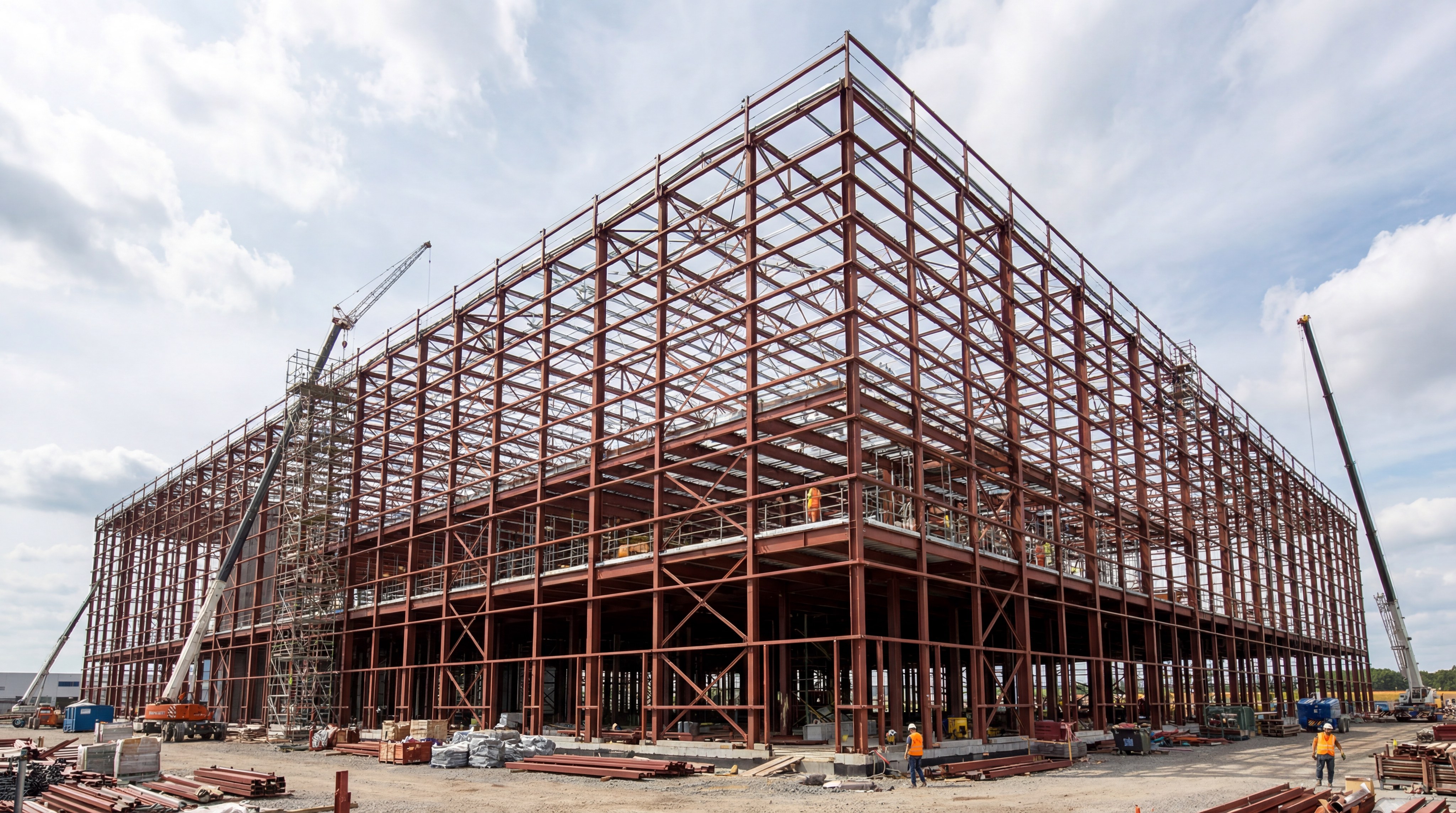
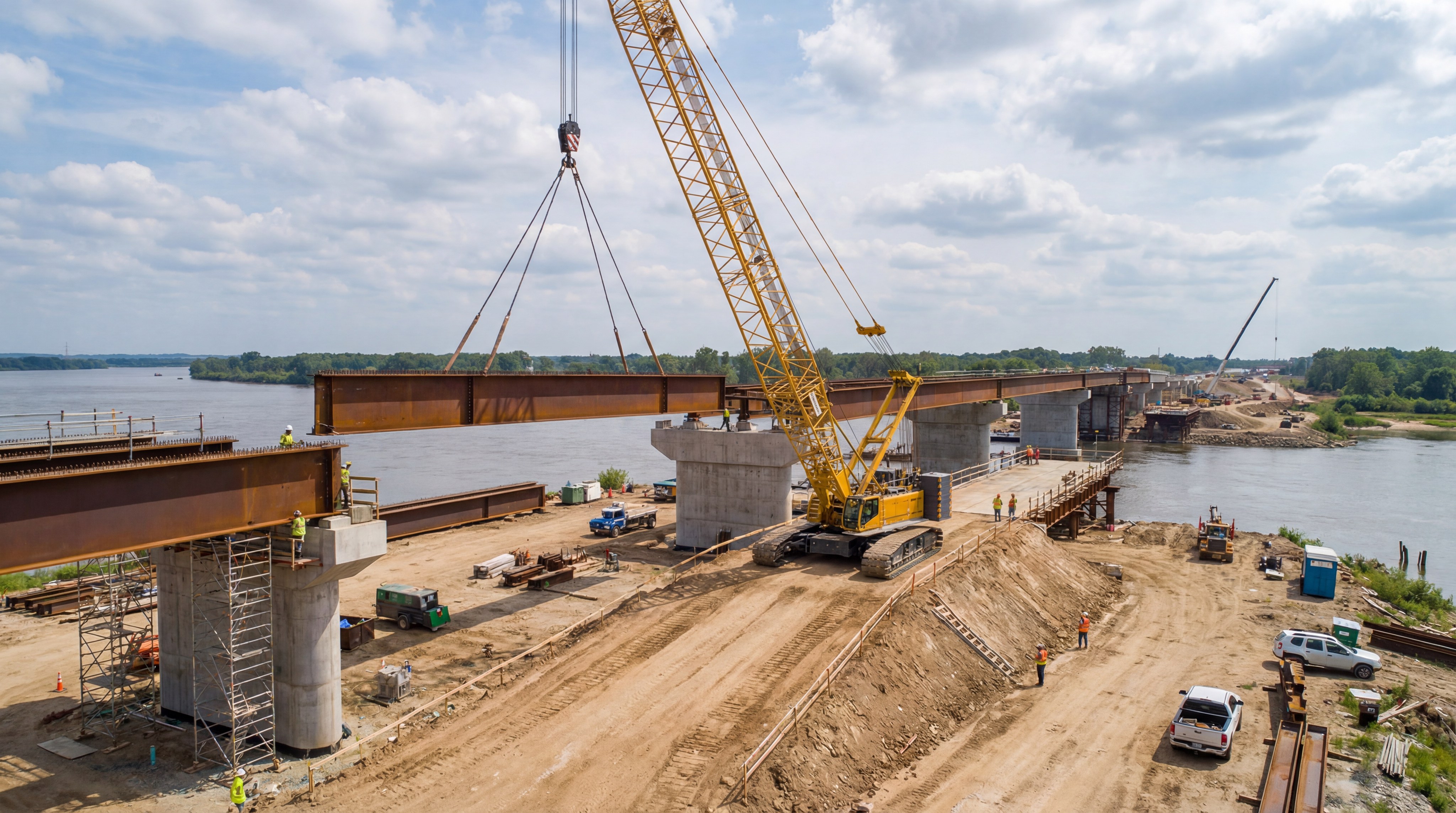
Industrial warehouses, commercial office towers, and large-scale infrastructure projects are the most common examples of this methodology. You will find that steel structure design is preferred in these scenarios due to its high strength-to-weight ratio and speed of assembly.
2.1. Industrial and Storage Facilities
In large-span warehouses, steel beams allow for vast open floor plans without the need for frequent vertical supports. These structures often utilize tapered members to optimize material usage over long distances.
But that’s not all.
- Warehouses often support crane systems.
- They require high resistance to wind uplift.
- Roof purlins must handle varying snow loads.
2.2. Commercial High-Rise Framing
Modern skyscrapers rely on composite steel beams to support heavy concrete floor slabs while maintaining a slim profile. This steel structure design approach maximizes the usable internal height for tenants and mechanical systems.
Here is why: It provides the necessary ductility to withstand seismic forces in active zones. Furthermore, it allows for easier integration of complex HVAC and electrical networks within the ceiling voids.
Key Takeaway:Steel is the material of choice when projects demand long spans, rapid construction timelines, and high seismic resilience.
Summary Table: Sector Applications
| Sector | Typical Beam Type | Key Benefit | |
|---|---|---|---|
| Industrial | Universal Beams | Unobstructed Space | |
| Commercial | Composite Sections | Reduced Floor Depth | |
| Infrastructure | Plate Girders | Extreme Load Capacity |
Understanding the specific application allows you to tailor the beam properties to the unique demands of the environment.
3. How to set the static steel structure design?
Setting the static design involves defining the beam’s span length and the nature of its supports. You must decide whether the member is simply supported, fixed at both ends, or continuous over several pillars. Correct steel structure design hinges on these boundary conditions because they dictate the distribution of internal stresses.
3.1. Defining Support Conditions
Pinned supports allow for rotation but prevent translation, which is the most common model for simple floor beams. If you require more rigidity, fixed supports can be utilized to reduce the mid-span bending moment.
Consider this:
- Simple supports result in higher mid-span moments.
- Fixed supports require complex, expensive connections.
- Cantilevers create high negative moments at the support.
3.2. Mapping the Tributary Area
You must calculate the exact floor area that transfers its load to a specific beam to avoid under-designing. Accuracy in steel structure design requires a deep understanding of how loads “flow” through the decking and secondary members.
Think about it. If the tributary width is miscalculated by even 10%, the beam could face premature failure.
Key Takeaway:The static model must accurately reflect the physical connections to ensure the calculated forces match real-world behavior.
Summary Table: Support Characteristics
| Support Type | End Rotation | Moment Transfer | Connection Complexity | |
|---|---|---|---|---|
| Pinned | Allowed | No | Low | |
| Fixed | Restrained | Yes | High | |
| Roller | Allowed | No | Low |
A precise static model is the only way to generate a reliable bending moment diagram for sizing.
4. What loads affect your steel structure design?
Dead loads, live loads, and environmental forces are the primary factors that impact your structural calculations. You must account for the weight of the steel itself plus any permanent or temporary actions the beam will support. Professional steel structure design categorizes these loads based on their duration and probability of occurrence.
4.1. Dead and Permanent Loads
Dead loads include the self-weight of the steel beam, the floor slab, and all permanent architectural finishes. You must also consider the weight of fixed machinery or heavy mechanical ducts that will remain throughout the building’s life.
Here are the components:
- Steel member self-weight.
- Concrete or timber decking.
- Ceiling and floor finishes.
- Permanent partitions.
4.2. Understanding Live and Transient Loads
Live loads are the transient weights of people, furniture, and movable equipment. In steel structure design, these values are typically determined by the building’s occupancy type as defined in regional codes.
The bottom line? You cannot guess these values; you must follow the minimum load requirements set by your local building department.
Key Takeaway:Accurate load identification prevents the catastrophic error of designing for a capacity that is lower than the actual demand.
Summary Table: Load Categories
| Load Type | Source | Variability | |
|---|---|---|---|
| Dead (G) | Structure/Fixed items | Low | |
| Live (Q) | Occupancy/People | High | |
| Environmental | Wind/Snow/Seismic | Seasonal/Random |
Correct load assessment serves as the input data for the critical load combination phase.
5. How to combine loads in steel structure design?
Load combinations involve applying mathematical factors to different load types to simulate the most critical scenarios. You use these combinations to check both the safety and the comfort of the structure. Effective steel structure design relies on these weighted scenarios to ensure the beam can handle the statistical peak of combined forces.
5.1. Ultimate Limit State (ULS) Factors
ULS combinations are used to prevent structural collapse by amplifying the loads with safety factors. You typically multiply dead loads by 1.2 and live loads by 1.6 to create a “worst-case” demand for strength verification.
It gets better. By factoring the loads, you create a buffer that accounts for unexpected material defects or minor construction errors.
5.2. Serviceability Limit State (SLS) Scenarios
SLS combinations focus on the daily performance of the beam, such as how much it deflects under normal use. In this part of steel structure design, you generally use unfactored (1.0) loads to check for user comfort and finish integrity.
- Use SLS for deflection checks.
- Use SLS for vibration analysis.
- Use SLS for cracks in finishes.
Key Takeaway:Load combinations ensure that the beam is safe under extreme conditions while remaining functional during daily operations.
Summary Table: Combination Logic
| Limit State | Focus | Load Factors | |
|---|---|---|---|
| Strength (ULS) | Safety/Collapse | Factors > 1.0 | |
| Service (SLS) | Comfort/Cracking | Factors = 1.0 | |
| Accidental | Fire/Impact | Specialized Factors |
Mastering load combinations allows you to move confidently into the material selection and section sizing phase.
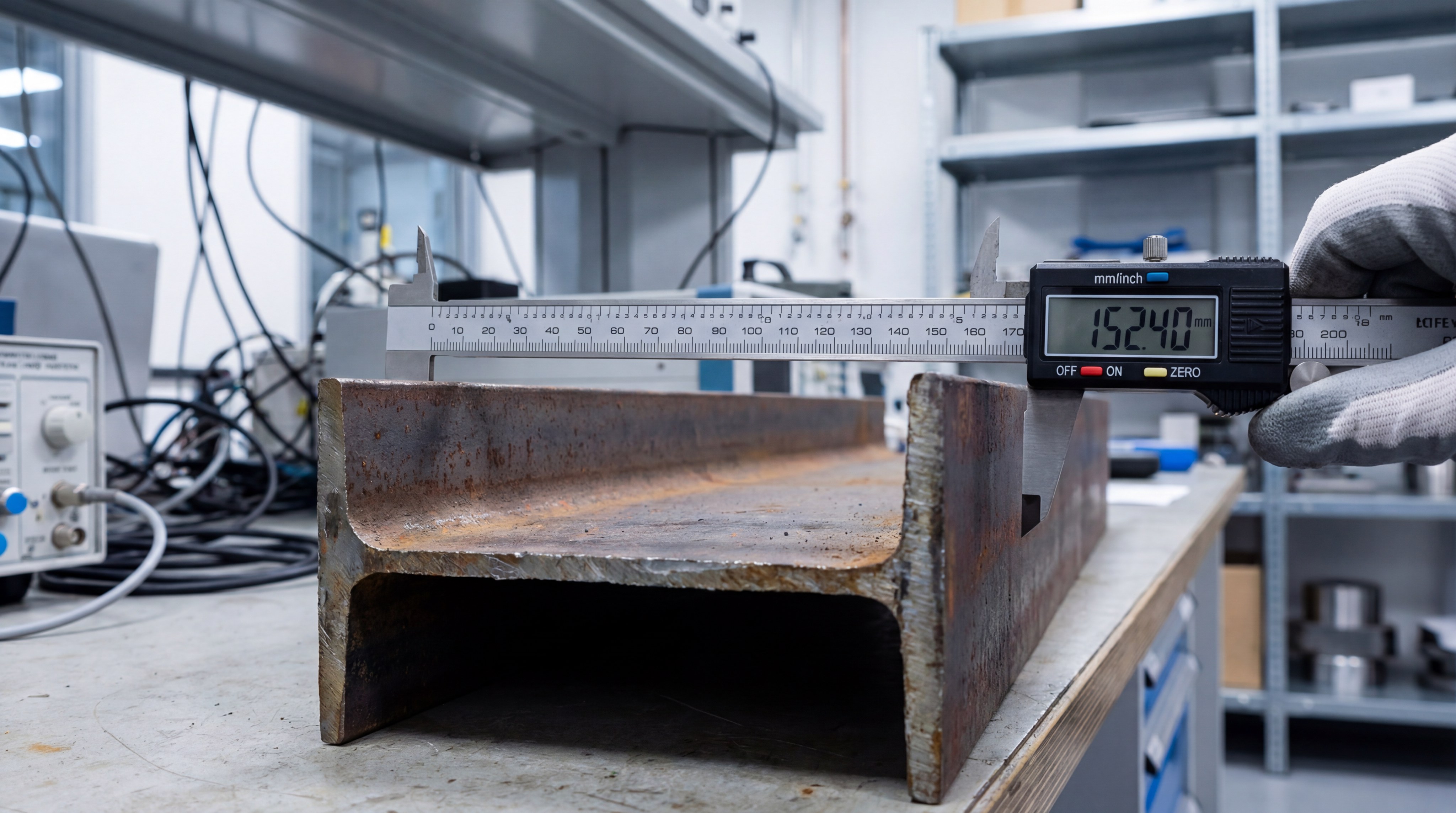
6. What are the key steel structure design properties?

Key properties include the yield strength of the metal and the geometric efficiency of the section shape. You must balance the material grade with the moment of inertia to satisfy both strength and stiffness requirements. Successful steel structure design optimizes these variables to provide the lightest possible member that meets all codes.
6.1. Material Grade and Strength
Steel is often specified by its yield strength, such as Grade 50 (50 ksi) or S355 (355 MPa). While higher grades offer more strength, they do not increase the material’s stiffness, which is a common misconception.
Here is why:
- High-grade steel allows for thinner sections.
- Stiffness (E) remains constant across all steel grades.
- Yielding occurs when applied stress exceeds the material’s limit.
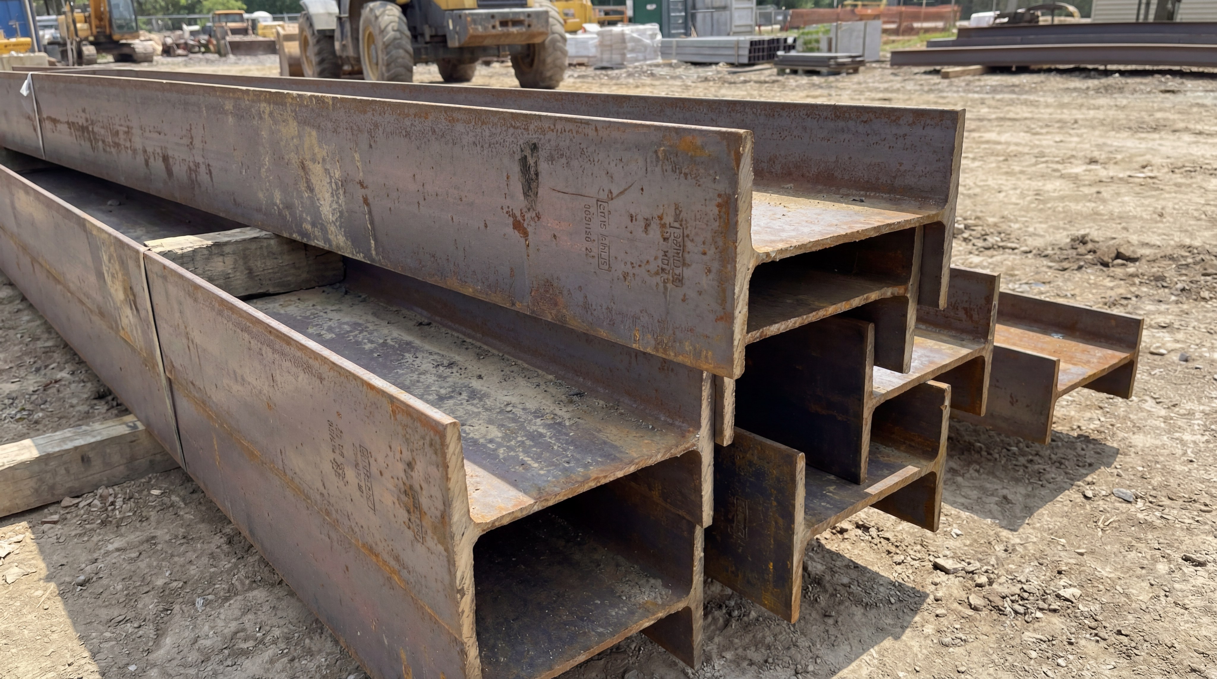
6.2. Geometric Section Properties
The shape of the beam determines how well it resists bending and twisting. In steel structure design, you focus on the section modulus for strength and the second moment of area for deflection control.
Now for the best part. Choosing a deeper beam is often more efficient than choosing a heavier, shallower one because stiffness increases with the cube of the depth.
Key Takeaway:Section properties are the bridge between theoretical forces and the physical reality of the steel member.
Summary Table: Critical Properties
| Property | Metric | Impact | |
|---|---|---|---|
| Yield Strength | Fy | Bending Capacity | |
| Section Modulus | Z or S | Elastic Strength | |
| Moment of Inertia | I | Deflection Control |
Selecting the right section is a balancing act between material costs and architectural space constraints.
7. How to classify sections in steel structure design?
Section classification is the process of checking if the thin parts of a beam will buckle before the material reaches its full strength. You must categorize sections based on the width-to-thickness ratios of their flanges and webs. In steel structure design, this step determines whether you can use plastic analysis or if you must stay within the elastic range.
7.1. Understanding Local Buckling
Local buckling occurs when a thin plate element fails under compression before the entire beam reaches its capacity. You must ensure that the flanges are thick enough to resist this phenomenon, especially in high-stress zones.
Think about it: If a flange is too slender, it will “ripple” and fail prematurely.
7.2. What are the four classes?
Sections are divided into Class 1 (Plastic), Class 2 (Compact), Class 3 (Semi-compact), and Class 4 (Slender). Professional steel structure design usually avoids Class 4 sections for primary beams because they require complex reduced-effective-area calculations.
- Class 1: Can form a plastic hinge.
- Class 2: Can reach plastic moment capacity.
- Class 3: Can only reach elastic yield.
- Class 4: Fails by local buckling early.
Key Takeaway:Classifying your section ensures that you are using the correct mathematical formulas for strength verification.
Summary Table: Classification Impact
| Class | Design Capacity | Ductility Level | |
|---|---|---|---|
| 1 & 2 | Plastic () | High | |
| 3 | Elastic () | Moderate | |
| 4 | Effective Section | Low |
A properly classified section provides the foundation for accurate internal force analysis.
8. How to find forces in a steel structure design?
Finding forces involves calculating the maximum shear and bending moments that occur along the beam’s length. You use the established loads and static model to generate diagrams that highlight critical stress points. In steel structure design , these peak values are the “demands” that your chosen steel section must exceed.
8.1. Calculating Moment and Shear
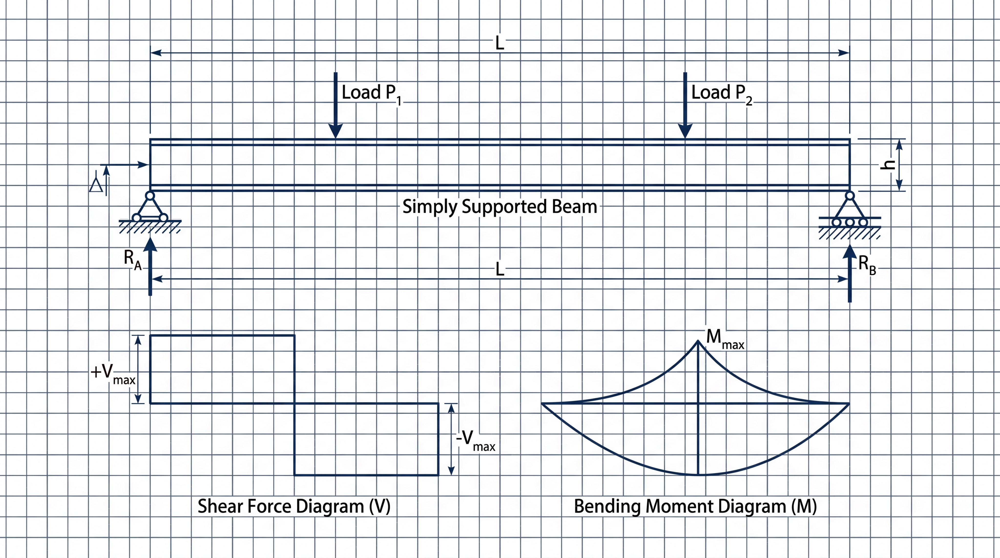
Maximum bending moments usually occur at the mid-span for simply supported beams, while maximum shear forces are found at the supports. You must solve the equilibrium equations to find these values for every load combination.
You might wonder: “How do I handle point loads versus uniform loads?” Uniform loads distribute the force evenly, whereas point loads create sharp peaks in your moment diagram.
8.2. Utilizing Force Diagrams
Visualizing the forces through shear (V) and moment (M) diagrams allows you to identify where the beam is most likely to fail. This stage of steel structure design is where you determine if the member needs extra reinforcement or local stiffeners.
- Look for the peak Mmax.
- Check for high shear at support reactions.
- Identify zero-moment points for potential splices.
Key Takeaway:Accurate force calculation is the only way to prove that your design can withstand the environmental demands.
Summary Table: Force Distribution
| Force Type | Maximum Location | Impact Area | |
|---|---|---|---|
| Bending Moment | Mid-span (typically) | Beam Flanges | |
| Shear Force | Near Supports | Beam Web | |
| Axial Force | Throughout (if tilted) | Whole Cross-section |
Once you have identified the maximum forces, you can proceed to the final verification of the member’s capacity.
9. How to verify bending in steel structure design?

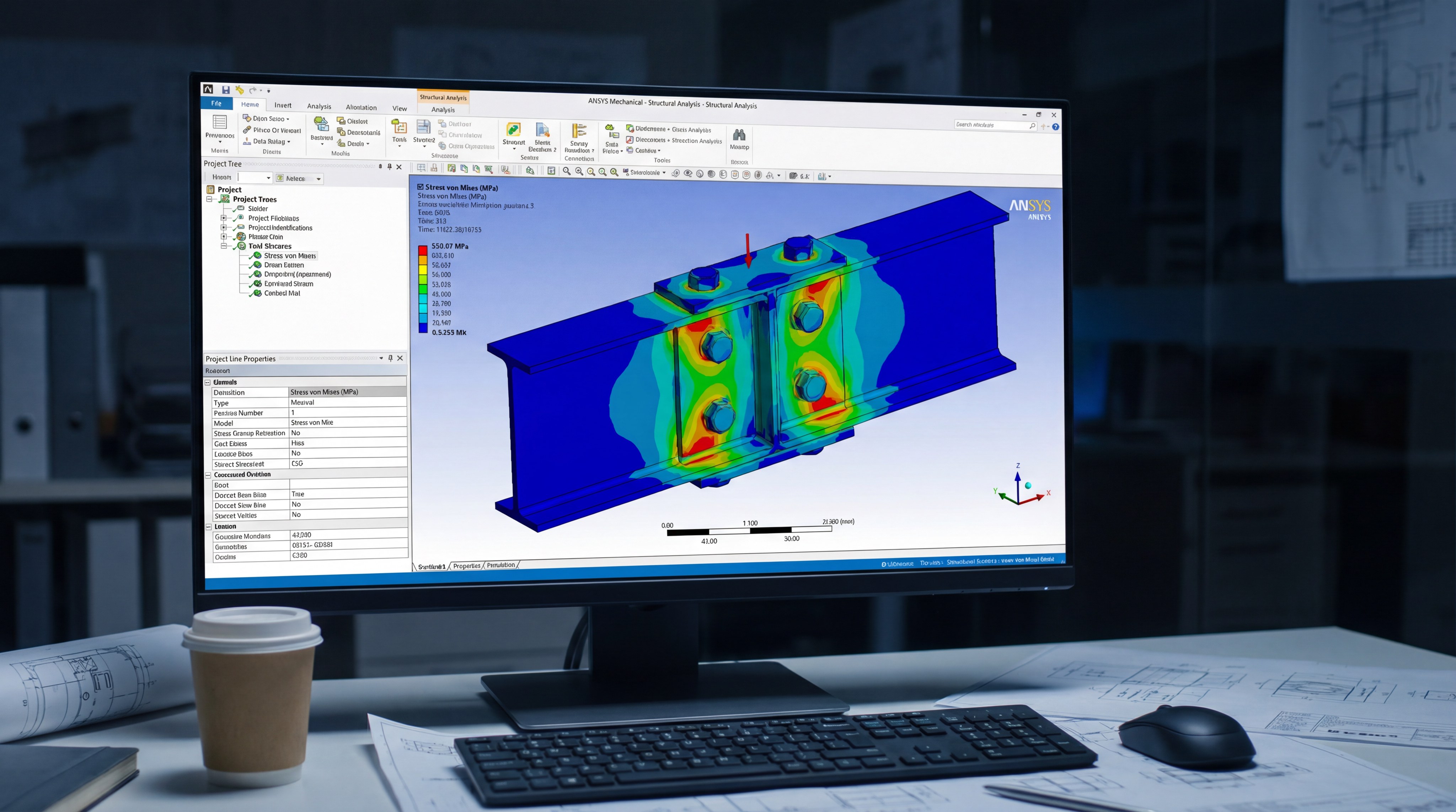
Verifying bending involves comparing the applied moment to the calculated resistance of your steel section. You must ensure that the “design strength” is always greater than the “required strength” to maintain a safe margin. This verification is the heart of steel structure design, confirming that the beam won’t yield or buckle under the ULS combinations.
9.1. Shear and Moment Utilization
Utilization is the ratio of demand over capacity; any value under 1.0 indicates a safe member. You should ideally target a utilization between 0.8 and 0.95 to ensure an economical yet safe steel structure design.
Now for the best part. Checking shear is just as vital as bending, as a thin web can fail by crushing or buckling at the beam ends.
9.2. How to ensure stability?
Even if the material is strong enough, the beam might fail if it is not laterally braced. You must verify that the compression flange is restrained against lateral-torsional buckling.
The result?
- Increased safety against twisting.
- Full utilization of material strength.
- Consistent performance under heavy loads.
Key Takeaway:The verification phase is the final “pass/fail” test that validates all your previous calculations and assumptions.
Summary Table: Verification Criteria
| Check Type | Formula Goal | Failure Mode | |
|---|---|---|---|
| Flexure | Mu≤ϕMn | Yielding/Buckling | |
| Shear | Vu≤ϕVn | Web Crippling | |
| Interaction | Combined Ratio < 1.0 | Combined Failure |
A successful bending check leads to the final assessment of how the beam moves and behaves under service.
10. Is deflection checked in steel structure design?

Deflection must be checked to ensure the beam does not bend excessively and damage fragile finishes like plaster or glass. You calculate vertical displacement under SLS loads to confirm it falls within the allowable limits, such as L/360. Professional steel structure design prioritizes these checks to guarantee user comfort and long-term building durability.
10.1. Setting Serviceability Limits
Deflection limits are defined by the type of materials the beam supports. For example, a beam supporting a sensitive glass facade requires much stricter limits than one supporting a standard metal roof.
Think about it.
- L/240 is common for roof members.
- L/360 is typical for floor members.
- L/600 might be needed for masonry supports.
10.2. What is Lateral Torsional Buckling?
LTB is a stability failure where a beam twists and moves sideways before reaching its full bending capacity. In your steel structure design, you must check the unbraced length to determine if the beam’s capacity must be reduced.
The result?
- Add lateral bracing to increase capacity.
- Choose a wider flange to resist twisting.
- Reduce the span to improve stability.
Key Takeaway:Stiffness and stability are often more restrictive than strength, frequently dictating the final size of the steel member.
Summary Table: Serviceability Checks
| Parameter | Limit Example | Mitigation Strategy | |
|---|---|---|---|
| Vertical Deflection | Span / 360 | Increase Section Depth | |
| Lateral Stability | Lb check | Add Secondary Bracing | |
| Vibration | Frequency > 4Hz | Increase Mass/Stiffness |
Finalizing these checks ensures that your beam is not just safe from collapse, but also perfectly suited for its daily purpose.
Conclusion
Navigating the complexities of steel beam engineering requires a disciplined approach to load paths, material properties, and stability checks. By following this systematic framework, you can transform complex architectural visions into durable, code-compliant realities. At Showhoo Building, we are committed to providing the highest quality structural components and engineering expertise to ensure your projects stand the test of time. Whether you are designing an industrial warehouse or a commercial high-rise, our team is ready to support your vision with precision-manufactured steel solutions.
To get expert assistance with your next project, contact us today .
Frequently Asked Questions
Can I use high-strength steel to reduce deflection?No, using a higher steel grade only increases the strength (yielding point), not the stiffness. Since the Modulus of Elasticity (E) is the same for all steel grades, you must increase the section’s Moment of Inertia to reduce deflection.
What’s the best way to prevent lateral torsional buckling?The most effective method is providing continuous lateral restraint to the compression flange, often achieved by connecting the beam to a floor slab or adding cross-bracing.
How do I determine the correct tributary area?You find the tributary area by identifying the halfway point between the beam in question and the adjacent parallel members on either side.
Why is section classification necessary?Classification is necessary to identify if a beam will fail due to local buckling of its thin components before the material reaches its full yield or plastic capacity.
Is it possible to design a beam without a software tool?Yes, simple beams can be designed using manual calculations and steel tables, but specialized software is highly recommended for complex load combinations and stability checks.